
PC RS422 INTERFACE

The RS422 communication interface circuit is designed to facilitate robust data transmission between devices while ensuring electrical isolation, which is crucial for protecting sensitive equipment from high voltage spikes or surges. The circuit operates by utilizing an isolation barrier, typically implemented with opto-isolators or transformers, to separate the transmitting and receiving sides of the interface from the PC.
Connector K1 serves as the interface point between the RS422 circuit and the PC's serial port. The connection is made through the DTR (Data Terminal Ready) and RTS (Request to Send) lines, which are standard control signals used in serial communication. The circuit derives its power for the PC side from these control lines, with the RTS line providing the positive voltage supply and the DTR line potentially used for the negative supply, depending on the circuit design.
The RS422 standard allows for differential signaling, which enhances noise immunity and allows for longer cable lengths compared to standard RS232 interfaces. The inclusion of an isolation circuit ensures that any voltage spikes on the RS422 side do not propagate back to the PC, thereby safeguarding it from potential damage.
The schematic diagram, referred to as Figure 1, illustrates the various components of the circuit, including the isolation elements, connectors, and necessary passive components like resistors and capacitors that may be used for signal conditioning and stabilization. This design not only enhances safety but also improves the reliability of data transmission in environments where electrical noise is prevalent.This interface circuit provides electrically isolated RS422 communication interface to the PC serial port the isolation circuit protect the PC from direct connection to hazardous voltages. Figure 1 shows the circuit diagram of RS422 interface. Connector K1 is linked to the serial port of the PC, power to the PC side of the circuit is derived from the signal lines DTR and RTS. Positive supply is derived from RTS and negative supply from the 🔗 External reference
Related Circuits
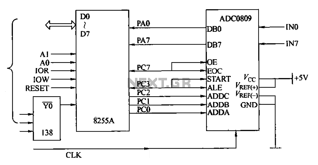
The ADC0809 is an 8-channel analog switch integrated with an 8-bit successive approximation analog-to-digital (A/D) converter. It supports the selection of eight input channels through address latch and encoder channel selection signals ADDA, ADDB, and ADDC. The address latch...
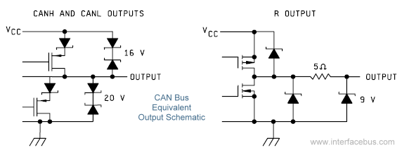
The Controller Area Network (CAN) Interface is a balanced (differential) two-wire interface that operates over Shielded Twisted Pair (STP), Unshielded Twisted Pair (UTP), or ribbon cable. Each node in the network utilizes a male 9-pin D connector. The bit...
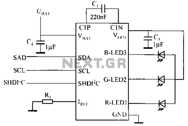
Watching the time on a mobile phone in the dark can cause discomfort due to the strong contrast between bright and dark backlighting. To address this issue, the "ICON" model is utilized, which operates in standby mode with a...
The PC parallel port can be easily damaged by wiring mistakes, short circuits, or the circuits connected to it. If the parallel port is integrated into the motherboard, as is the case with most computers, repairs can be expensive....
Below are three examples of controlling a relay from the PC's parallel printer port (LPT1 or LPT2). Figure A shows a solid-state relay controlled by one of the parallel port data lines (D0-D7) using a 300-ohm resistor and a...
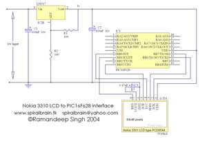
This project demonstrates the interfacing and operation of the Nokia 3310 LCD using the PIC16F628 microcontroller. The programming is executed in Hi-Tech C, with the character table incorporated within the source code. The Nokia LCD features a resolution of...