
I2C control interface includes RGB LED Driver circuit
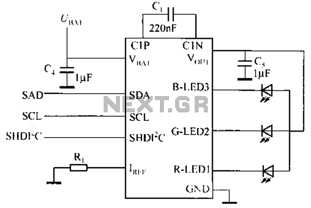
The described circuit leverages the NCP5602 RGB LED driver IC to manage LED brightness effectively in low-light conditions. The PWM control signal generated by the processor modulates the brightness of the LED backlight according to ambient lighting conditions, enhancing user comfort. The I2C interface allows for seamless communication between the processor and the NCP5602, enabling the selection of different operational modes, including the energy-efficient ICON mode.
In the normal backlight mode, the LED current is adjustable, providing flexibility in brightness settings based on user preferences or environmental factors. The transition to ICON mode is a critical feature that minimizes power consumption while maintaining visibility on the display. By using a fixed current of 450 µA for the LEDs in ICON mode, the circuit ensures that the display remains legible without straining the user's eyes.
The design of the circuit should incorporate appropriate filtering and decoupling capacitors near the NCP5602 to ensure stable operation. Additionally, the layout must consider thermal management, as LED drivers can generate heat during operation. Proper heat dissipation techniques, such as using thermal vias or heat sinks, may be necessary depending on the application.
The overall architecture of this circuit can be integrated into various portable devices, enhancing user interaction in low-light environments while conserving battery life. This implementation of the NCP5602 demonstrates the importance of optimizing display technologies for modern electronic devices, balancing performance with user comfort and energy efficiency.Have you ever in the dark watching time from the mobile phone In this case the bright and dark backlit strong contrast will make the eyes uncomfortable, which requires the use of "ICON" model "that is in standby mode with a slight current time, or user-defined image is displayed on the external LCD panel. If this must be done through PWM brightness control, the processor must produce a continuous low frequency PWM signal in the entire standby mode, NCP5602, this feature is the use of a hardware manner to achieve, and to be initiated by the figures in the table command with each I2C control interface typical RGB LED driver chip application circuit as shown. Typical RGB LED driver IC application circuit with each I2C control interface Driven by the processor to the chip data byte B5 it represents state ICON mode, when B5 is LOW, it indicates that the use of the normal backlight mode, each LED current can be adjusted between 0 ~ 30mA ; when B5 is HIGH "will start ICON mode, and will only 450 A of current to two LED connected in one on the ICON NCP5602 current mode is a fixed value, but similar NCP5612 on the product, this current can be controlled by single-wire communication protocol.
Related Circuits
This circuit serves as a decorative element or indicator, featuring adjustable flashing or dancing speeds of LEDs and the ability to create various light patterns. It consists of two astable multivibrators: one formed by transistors T1 and T2, and...
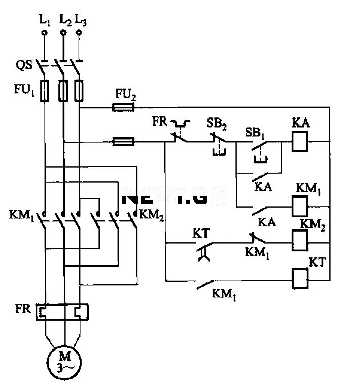
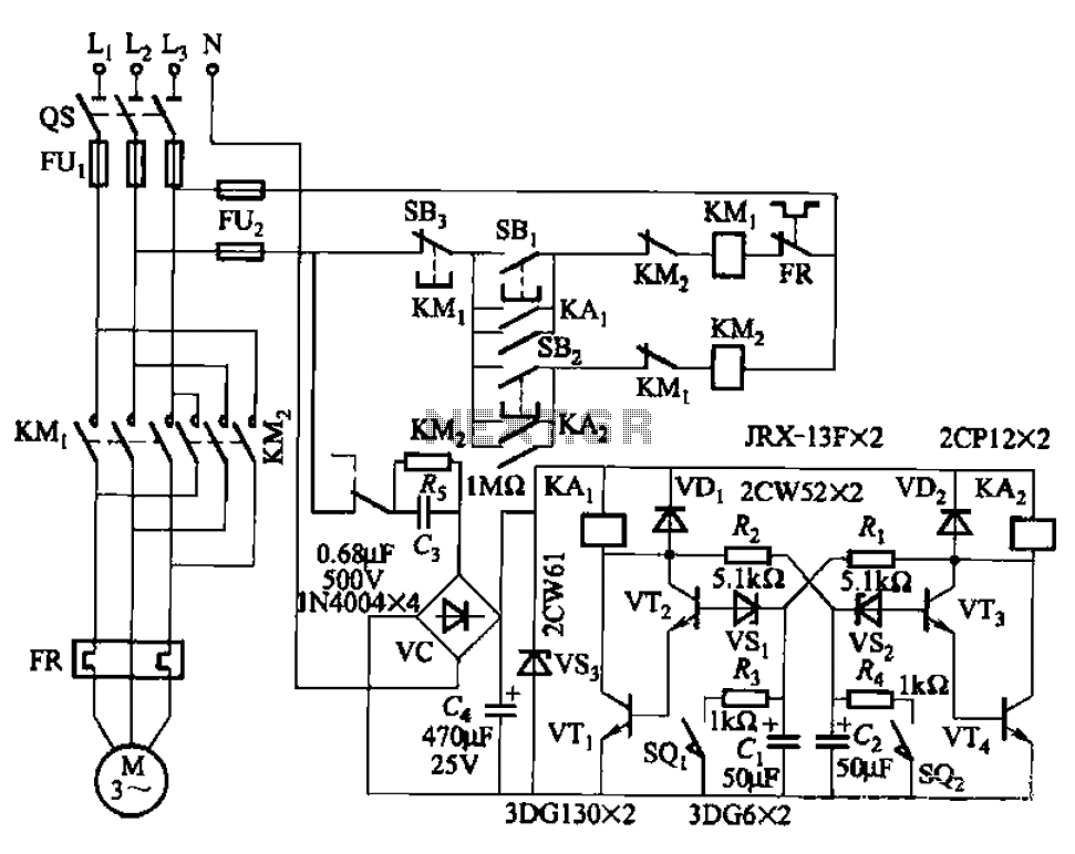
The circuit illustrated in Figure 3-127 utilizes a time relay (KT) in place of a speed relay. The timing duration is adjustable and typically set between 1 to 2 seconds. This circuit is designed to operate effectively in dusty...
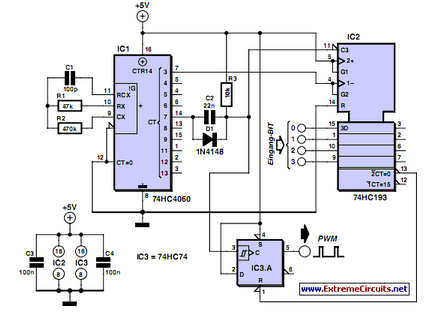
PWM waveforms are frequently utilized to regulate the speed of DC motors. The duty cycle of the digital waveform can be defined using an adjustable parameter. PWM (Pulse Width Modulation) is a technique employed to control the power delivered to...
Prototype 2 utilizes a common base to control various elements. This iteration includes a button that activates the tone only when pressed, along with a rotary potentiometer for volume adjustment. The circuit incorporates an Analog Devices ADXL3xx accelerometer that...
The circuit illustrated in Figure 3-72 employs a deformable bistable reversing motor control mechanism that automatically initiates and halts operation during a user-defined time delay. This feature is designed to safeguard the motor from potential impacts during the reversing...
An automatic recording telephone interface circuit is presented, featuring an automatic answering and recording function that requires a reprovisioning or a small solid-state recording chip. The circuit is straightforward, with a quiescent current of less than 20 µA, allowing...
Warning: include(partials/cookie-banner.php): Failed to open stream: Permission denied in /var/www/html/nextgr/view-circuit.php on line 713
Warning: include(): Failed opening 'partials/cookie-banner.php' for inclusion (include_path='.:/usr/share/php') in /var/www/html/nextgr/view-circuit.php on line 713