
PCB exposure box Based on ATmega8 AVR microcontroller

The system architecture comprises a microcontroller-based control unit interfacing with a relay module, which manages the AC power supply to the lamp system. The relay acts as a switch controlled by the microcontroller, allowing for safe operation of the high-voltage components. The microcontroller's GPIO pins are configured to read the input from the SET and START/STOP buttons and to drive the 7-segment LED displays, providing a user-friendly interface for countdown management.
The countdown logic is implemented in the firmware, ensuring that the user can easily set the desired time. The system employs debouncing techniques for button presses to avoid erroneous readings. When the countdown is initiated, the microcontroller continuously monitors the timer and updates the display until it reaches zero, at which point it deactivates the relay, cutting power to the lamp system, and triggers an audible alert.
The lamp modules utilize a combination of starters and ballasts to ensure proper ignition and operation of the fluorescent lamps. The design incorporates safety features, including fuses and isolation measures to protect the user from high voltages generated during the lamp ignition process. The layout of the components within the box is optimized for thermal management and accessibility, ensuring that the system operates efficiently and safely over extended periods.
In summary, this project integrates electronic design principles with practical applications, enabling effective control of a lamp system for photochemical and pest control purposes. The use of microcontroller technology enhances functionality, allowing for precise countdown management and user interaction while maintaining safety and reliability.I describe the procedure I followed to build the Box, the Lamp System and the Countdown System which is based on the AVR mega8 microcontroller. Four blacklight lamps, 15W each, emit radiation at the region of UVA, with a peak around 350nm where the thin surface above the copper of the photosensitive board, is.
sensitive. The lamps are taken by two and are connected in series thus shaping two similar modules. Each module has its own ballast and can be connected to 220V AC via a relay. A microcontroller counts a user defined countdown and upon reaching zero activates a relay. The time remaining is displayed on four 7-segment led displays. The maximum countdown is 99 minutes and 59 secs. The desired countdown is entered using only two buttons, SET and START/STOP. Short term push of the SET button will increase the current digit while prolonged push will change the digit from secondss to decades of seconds, to minutes and so on. Pushing once the START/STOP button, will make the MCU accept the desired countdown. Pushing the START/STOP button one more time, will start the countdown and connect the lamp system to 220V AC, via the relay.
If START/STOP button is pushed again before countdown reaches zero, the lamp system will be deactivated. When the countdown reaches zero the lamp system is deactivated and a 3 seconds beep is sounded. The timer remembers the last used countdown and uses it as default every time the system is switched on.
You are gonna need a wooden box with dimensions aproximately 50x30x60 cm3. The box must have an extra room for hosting the countdown board and the two ballasts. The height of that room, that is the distance between the bottom of the box and the shelf, can be 5-8 cm. On the one side of the shelf will be installed the four starter bases and on the other side the four lamps along with their G13 bases.
Here there is a very detailed description on how to build your own box, upon which I relied to decide the dimensions of my box. However the final design I used is the same as Papanikolaou`s box in his Darkroom Timer project. Many thanks to both of them! 4 x 15W Black Light UVA fluorescent lamps with a peak of radiation at ~350nm. Those lamps are suitable for photochemical procedures and can usually be used in insect killing. Examples are F15W/T8/BL from Syllvania and Actinic BL from Phillips There are twoidentical modules connected in parallel.
In each module, initially, the AC current flows through the two starters and the ballast. After a while one of the starters goes open-circuited and the current in the circuit is halted. This brings the ballast inductor in an extremely uncomfortable situation and it reacts violently developing a great voltage across its terminals. The value of the voltage can be as large as some kV and that is exactly what the fluorescent lamps need in order to be turned on.
After that transition effect the voltage accross each lamp gets stabillized around the 50~60V which is the lamp`s operation voltage shown in the manuals. Second, on the other side of the shelf, I screwed the eight G13 lamp holders, having first, drilled the holes needed by the wires to join the lamp bases with the starter bases.
As for the Software part I wrote the code in C using the winAVR and avr-gcc plugin along with avrStudio. Using ProteusVSM I tested the code in simulation environment which saved me a lot of effort and time.
Then I downloaded the hex code to the chip with the STK500. I strongly recommend 🔗 External reference
Related Circuits
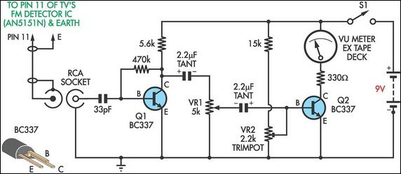
This circuit was designed to assist in the installation of TV antennas. The signal is monitored using a small portable TV set, and this circuit monitors the output of the TV's FM detector IC via a shielded lead. To...
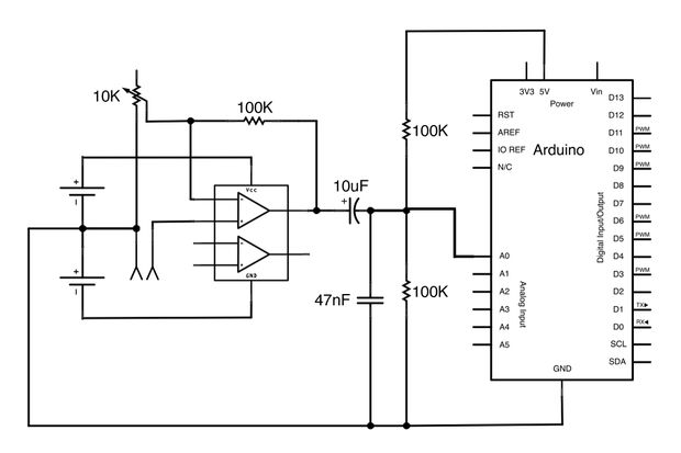
This Arduino-powered vocal effects box pitch shifts and distorts incoming audio signals to produce a wide variety of vocal effects. This project serves as an experiment with real-time digital signal processing using Arduino. It samples an incoming microphone signal...
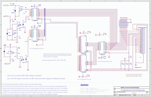
The following schematic illustrates the design of a Parallel Port Interface Circuit Diagram utilizing the 74HCT373. The 74HC/HCT373 are high-speed silicon-gate CMOS devices that are pin-compatible with low-power Schottky TTL (LSTTL). This parallel port interface circuit can drive 256...
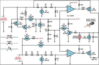
Improved Vibrating Battery Tester. This circuit is based on the LM393 integrated circuit. Features include the ability to test AAA, AA, C, and D cells. The Improved Vibrating Battery Tester utilizes the LM393, a dual comparator IC, to accurately assess...
A simple remote-controlled autocue system was designed using materials salvaged from an old bin, including an outdated P4 laptop, a broken USB keyboard, and a piece of plexiglass. A foot switch is utilized to control the scrolling of the...
Standard serial interfacing of a microcontroller (TTL) with a PC or any RS232C standard device requires a TTL to RS232 level converter. A MAX232 is used for this purpose. It provides a 2-channel RS232C port and requires external 10µF...