
TV Relative Signal Strength Meter PCB

The circuit operates by utilizing a small portable TV set to monitor the signal strength received from the antenna. The core component of this setup is the FM detector integrated circuit (IC) within the TV, which converts the RF signals into an audio frequency that can be interpreted by the meter. The output from the FM detector IC is accessed through a shielded lead to minimize interference from external sources, ensuring accurate readings.
Calibration of the circuit is critical for optimal performance. The trimpot VR2 is used to zero the meter, establishing a baseline reference point. This step is essential for ensuring that subsequent readings accurately reflect the signal strength being received. The sensitivity control, trimpot VR1, allows for flexibility in the measurements. It can be adjusted to provide a preset reading of 0 dB or calibrated to display millivolt readings, depending on the user's preference or specific requirements of the installation.
To achieve the best reception, the antenna's orientation must be adjusted based on the readings from the meter. The goal is to find the position that yields the lowest reading on the meter, which indicates FM quieting. This phenomenon occurs when the signal-to-noise ratio is at its highest, resulting in a clearer audio output. By following this procedure, users can effectively optimize the placement of their TV antennas, ensuring the best possible signal reception for their viewing experience.
This circuit design provides a practical solution for installers and users alike, facilitating the installation process and enhancing the overall performance of TV antennas.Circuit This circuit was designed to assist the installation of TV antennas. The signal is monitored using a small portable TV set and this circuit monitors the output of the TV`s FM detector IC via a shielded lead. To initially calibrate the meter, adjust trimpot VR2 to zero the meter. Trimpot VR1 is a sensitivity control and can be set for a pre set reading (ie, 0dB) or can be calibrated in millivolts. Rotating the antenna for a minimum reading on the meter (indicating FM quieting) gives the optimum orientation for the antenna. 🔗 External reference
Related Circuits
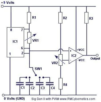
Construct a signal generator using readily available components. It should produce a square wave with variable frequency and adjustable pulse width. This device can be utilized for various applications, including DC motor speed regulation, dimming of lamps or LEDs,...
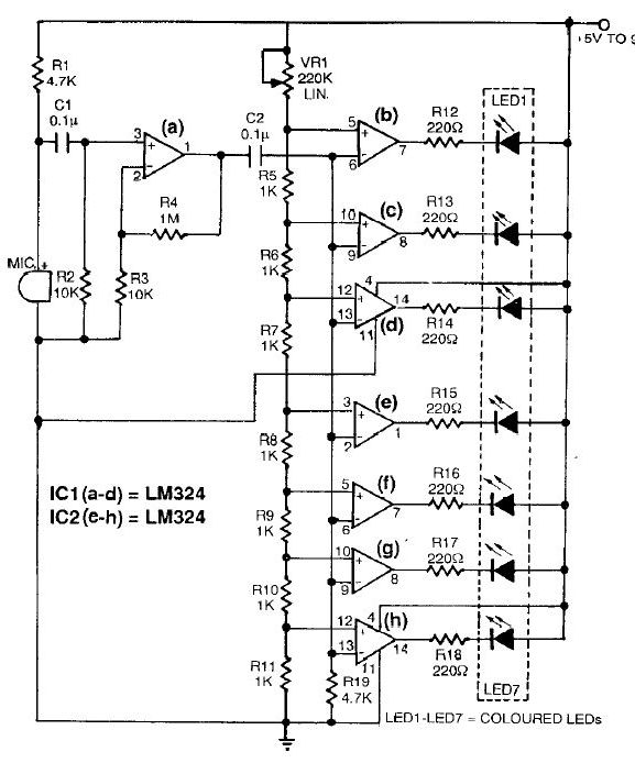
This sound level meter circuit can be used to control the intensity of a sound recording or in a disco. It has 5 measurement domains between 70 and 120 dB. The sound level meter circuit is designed to measure sound...
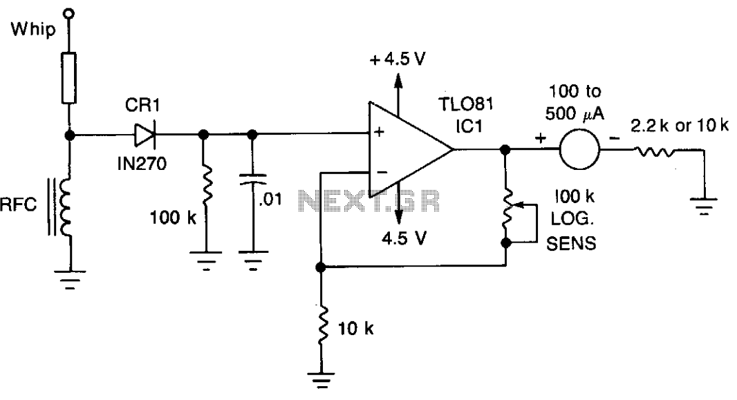
A TL081 operational amplifier (IC1) is utilized to enhance sensitivity. The RF signal is detected by CR1 and subsequently amplified by IC1. Full-scale sensitivity is adjusted using a 100-ohm potentiometer. The circuit employs a TL081 operational amplifier, known for its...

The micro ampere meter presented here functions as a DC millivolt meter. It achieves full-scale deflection with a 0.1V input. The current to be measured flows through a known resistance R, and the voltage drop across this resistance is...
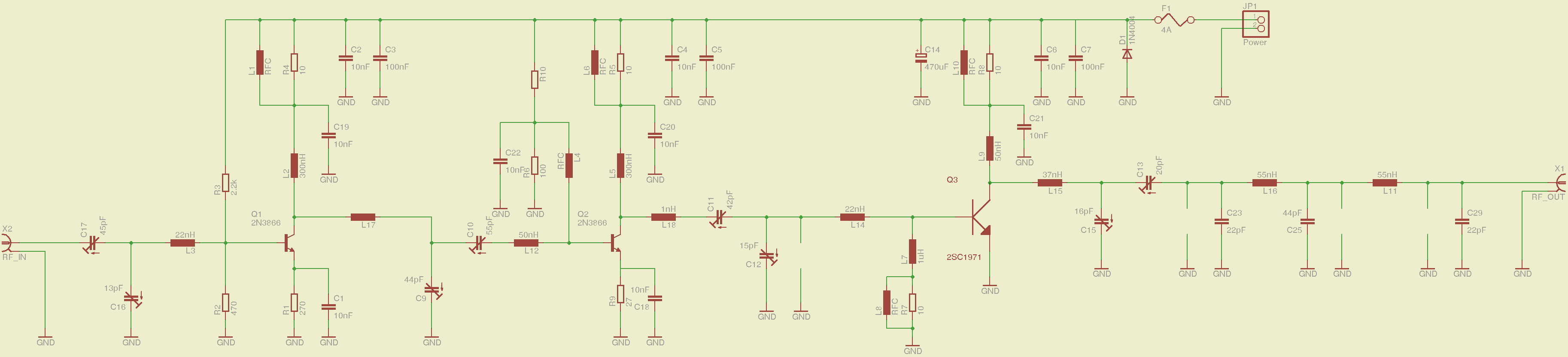
A 2-meter ham radio transceiver that incorporates all necessary circuitry, specifically including a voltage-controlled oscillator (VCO) and phase-locked loop (PLL) for frequency synthesis, a low noise amplifier (LNA) for the receiver front-end, a power amplifier (PA) for the radio...
Here is a simple technique for measuring frequencies over quite a wide frequency range and with acceptable accuracy limits using a PC. It follows the basic technique of measuring low frequencies, i.e. at low frequency, period is measured for...