
Peak detect and hold

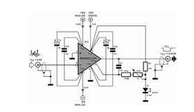
This circuit utilizes a 741 operational amplifier in a configuration designed for voltage tracking and capacitor charging. When the input voltage surpasses the voltage stored in the capacitor, the operational amplifier's output transitions to a high state, activating the diode. This action allows the capacitor to charge up to a level slightly lower than the input voltage, accounting for the forward voltage drop inherent in the diode. This charging mechanism is crucial for applications that require precise voltage levels to be maintained.
When the input voltage falls below the capacitor's voltage, the operational amplifier's output shifts to a negative state, effectively turning off the diode. This prevents any reverse current flow from the capacitor, thus preserving its charge. The strategic use of a high input impedance buffer stage (IC2) is essential for maintaining the integrity of the capacitor's charge. This buffer stage ensures that the subsequent circuit stages do not load the capacitor, which could lead to undesired discharge and affect the overall performance of the circuit.
The ability to reset the circuit is facilitated through the integration of a FET or similar high impedance device. This component can be connected across the capacitor, allowing for a controlled discharge when necessary, without significantly affecting the circuit's impedance characteristics. The design thus ensures that the capacitor can be recharged and reset efficiently while maintaining high accuracy in voltage tracking applications. Overall, this circuit exemplifies a robust approach to managing voltage levels and capacitor behavior in electronic systems.If the voltage at the input exceeds the voltage on the capacitor, then the output of the 741 goes positive, the diode conducts, and the capacitor is charged up to the input voltage-forward voltage drop of diode. When the voltage at the input is less than that on the capacitor, the output of the 741 goes negative, and the diode cuts off
To prevent the capacitor from discharging through the input resistance of the next stage, a high input impedance buffer stage (IC2) is used. The circuit can be reset by means of a FET or similar high impedance device connected across the capacitor.
Related Circuits
More: A comprehensive electronic schematic description is required to provide an overview of the circuit's functionality, components, and operation. The schematic should include a clear representation of the electronic components involved, such as resistors, capacitors, diodes, transistors, integrated circuits,...

The circuit utilizes a dual operational amplifier integrated circuit (IC), specifically the 1458, which contains two separate op-amps within a single package. In this configuration, the first op-amp functions as a voltage follower, directing its output to charge capacitor...
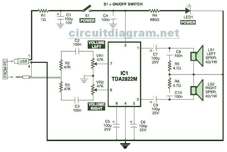
USB Powered Stereo PC Multimedia Speaker Circuit Diagram. This circuit is powered by a 5V DC source obtainable from the USB port of a computer. When the electrical power switch S1 is turned to the "on" position, the 5V...
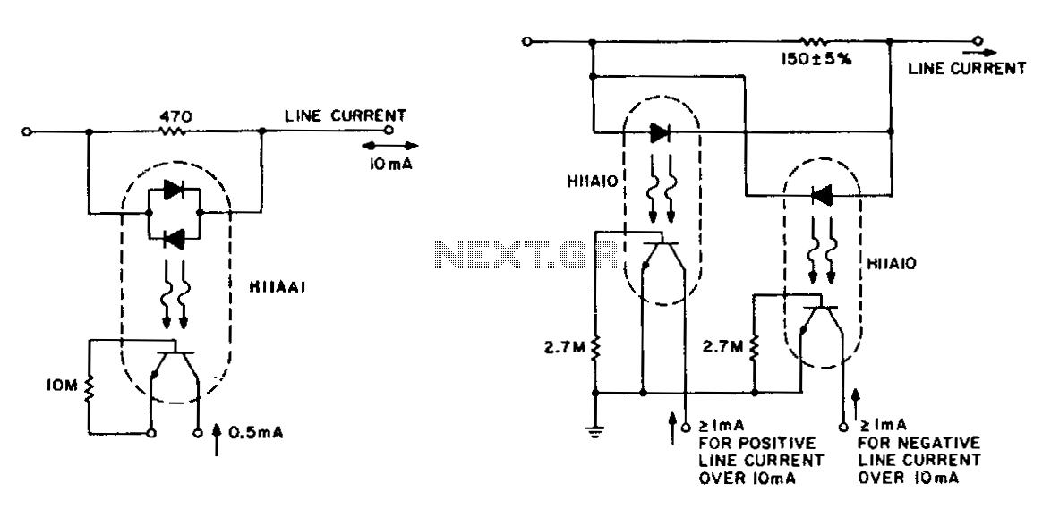
The detection of line-current flow and its indication at an electrically remote point is essential for line status monitoring in various telephone systems and auxiliary systems. The monitoring circuit must minimally unbalance or load the line, while also being...
Dynamic flip-flops disregard input pulses that are shorter than 40 ns or do not conform to TTL voltage levels. Consequently, TTL flip-flops are not well-suited for certain applications. Dynamic flip-flops are a specific type of sequential logic circuit that utilize dynamic...
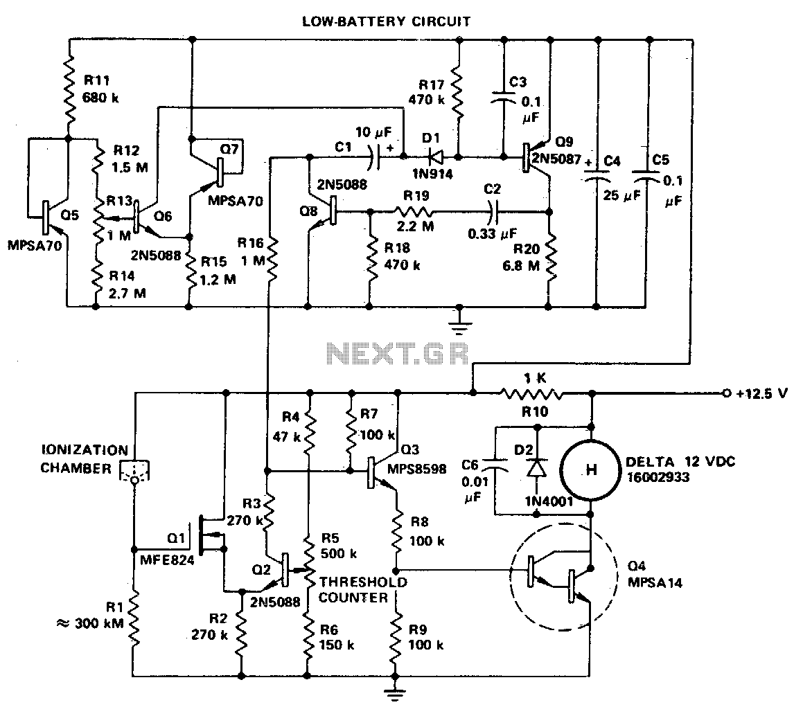
The smoke alarm signal must be continuous rather than pulsating; therefore, the slightly less expensive all-discrete transistor version of the MC14572 may be utilized. The MC14572 is a versatile integrated circuit commonly used in smoke detection systems. This device is...