
Simple Peak Detector Circuit schematic with explanation

The circuit design effectively employs the 1458 dual operational amplifier to achieve peak voltage detection from an input waveform. The first op-amp, configured as a voltage follower, ensures that the output voltage closely follows the input voltage, allowing for efficient charging of capacitor C1. This configuration is crucial for accurately capturing the peak voltage of the input signal, as the voltage across C1 will reflect this maximum value.
The diode D1 plays a vital role in preventing the discharge of C1 back into the op-amp, ensuring that the capacitor retains its charge after reaching the peak voltage. This characteristic is particularly important in applications where the peak voltage must be maintained for further processing or analysis.
The second op-amp serves as a buffer, isolating the capacitor from the subsequent circuitry. This buffering action minimizes any load effects that could result in voltage drops, thereby preserving the integrity of the voltage stored in C1. This feature is essential for applications requiring precise voltage levels.
The reset switch allows for manual intervention to discharge the capacitor. This functionality is important for applications that need to detect new peak voltages at irregular intervals. By discharging C1, the circuit can be reset and prepared to capture the next peak voltage accurately.
Overall, this circuit design demonstrates an efficient method for peak voltage detection using a dual op-amp configuration, ensuring accurate voltage tracking and minimal signal degradation. The combination of a voltage follower, buffer, and reset mechanism provides a robust solution for various electronic applications requiring peak voltage monitoring.The circuit uses a dual operational amplifier IC, the 1458, which is a single IC package that houses two individual op-amps. In this circuit, the first op-amp is used as a voltage follower whose output is used to charge the capacitor C1 through D1.
As such, the voltage to which capacitor C1 charges up to is the maximum voltage that the input wavef orm reached, i. e. , its peak voltage. The second op-amp of the 1458 is used as a buffer that outputs the capacitor voltage with negligible loss in the capacitor charge. The reset switch is used to discharge the capacitor if a new input peak voltage needs to be detected.
🔗 External reference
Related Circuits
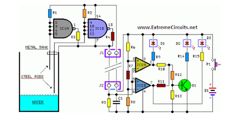
Simple two-wire remote monitoring unit with a three-LED level display, powered by a 9V battery. The entire project was developed at the request of a friend. The remote monitoring unit is designed to provide a straightforward solution for level indication...
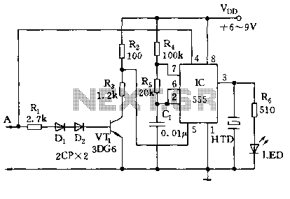
The circuit utilizes a 555 timer along with resistors R4, R5, and capacitor C1 configured in a controllable multivibrator mode. This setup forces the reset terminal (pin 4) to a specific state, allowing for control of the external logic...
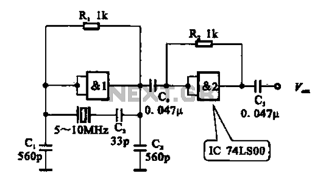
A crystal oscillator circuit comprises various gates as illustrated in the provided figures. Figure (A) represents a crystal oscillator circuit operating at 1 MHz, while figure (B) depicts a 20 MHz crystal oscillator circuit. Figure (C) shows a variable...
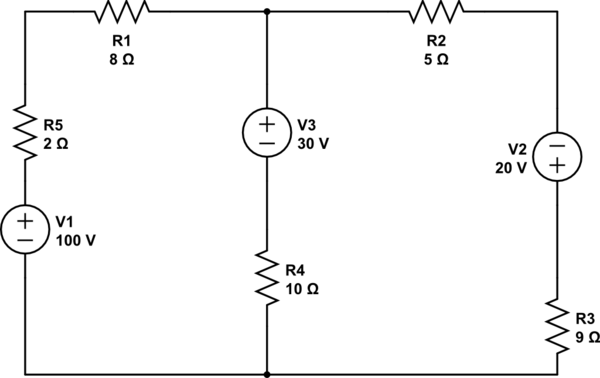
Using the superposition theorem, it is necessary to determine the current at all three nodes of the circuit. The current from the source, denoted as i_1, represents the current through V1 when other voltage sources are shorted out, in...
This simple alarm circuit is designed for use in a combined garage and rumpus room. It can be assembled on Veroboard and utilizes a single integrated circuit (IC) along with a few inexpensive components. The circuit is based on...

R4 prevents the output voltage from drifting toward one of the supply rails of the operational amplifier. It is understood that R4 should have a high resistance, although the reason for this is unclear. The schematic appears to be...