
PFC Switching Power Supply

The PFC Switching Power Supply Circuit is designed to enhance the efficiency of power conversion while reducing harmonic distortion at the input stage. This circuit typically employs a PFC controller, which regulates the input current to follow the input voltage waveform, thereby improving the power factor towards unity.
The circuit can be implemented using a boost converter topology, where the input AC voltage is rectified to DC and then boosted to a higher DC voltage level. The PFC controller continuously monitors the input voltage and adjusts the duty cycle of the switching element, usually a MOSFET, to maintain the desired power factor.
Key components of the circuit include:
1. **Rectifier**: Converts AC input voltage to pulsating DC. Often a bridge rectifier is used to handle both halves of the AC waveform.
2. **Boost Converter**: Comprises an inductor, a diode, a switch (MOSFET), and a capacitor. The inductor stores energy when the switch is closed and releases it when the switch is open, boosting the voltage.
3. **PFC Controller**: This integrated circuit (IC) monitors the input voltage and adjusts the switching duty cycle to achieve a sinusoidal input current that is in phase with the input voltage.
4. **Filter Capacitor**: Smooths the output voltage to reduce ripple, ensuring stable operation of downstream components.
5. **Feedback Loop**: Provides real-time adjustments to the PFC controller based on the output voltage and current, contributing to overall circuit stability.
The design is particularly suited for applications requiring compact form factors, such as 1U rack-mounted systems, where space is limited. Additionally, the minimization of input harmonics is crucial for compliance with regulations such as IEC 61000-3-2, which governs harmonic emissions in electrical equipment.
Overall, this circuit design not only enhances energy efficiency but also contributes to a cleaner power supply, reducing the environmental impact of electronic devices.The following circuit shows about PFC Switching Power Supply Circuit Diagram. Features: suited for 1U (1.75-inch), minimise input harmonic .. 🔗 External reference
Related Circuits
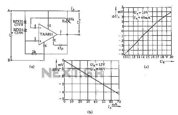
The regulator circuit adjusts the output voltage based on the potentiometer Rp and exhibits linear regulation characteristics. The output voltage Ua varies with the load current Ia, ranging from 0 to 70 mA, as illustrated in Figure (C) for...

The SA607 is a low voltage, high-performance monolithic FM intermediate frequency (IF) system that includes a mixer, oscillator, two limiting intermediate frequency amplifiers, a quadrature detector, a logarithmic received signal strength indicator (RSSI), a voltage regulator, and audio and...
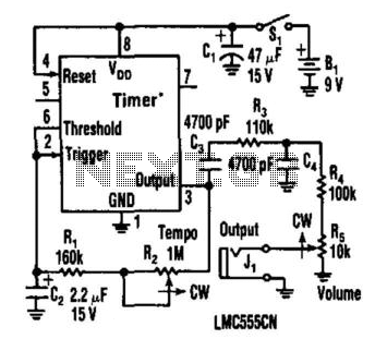
This metronome operates on a current of only 0.25 mA, making it suitable for battery-powered applications. It offers a tempo range from 34 to 246 beats per minute. The circuit can utilize a CMOS timer, such as the LM555...
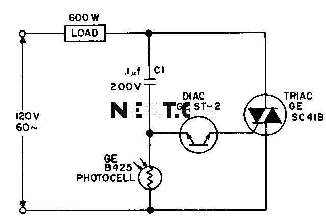
For a dark photocell with high resistance, the voltage across the diac rises rapidly in response to the line voltage due to the current flowing through capacitor C1, which triggers the diac early in the cycle. When the resistance...
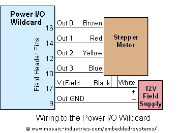
For optimal efficiency, set MAX_STEPPERS to the number of stepper motors being controlled, with a maximum limit of four. Motors are identified by indices 0, 1, 2, and 3. On the QCard, there is a trade-off between the number...
Stabilized DC Power Supply with Short-Circuit Indication. The circuit provides four distinct regulated DC outputs (12V, 9V, 6V, and 5V) along with an unregulated 18V DC output, selectable via a rotary switch S2. The chosen output is displayed on...