
Linear power supply circuit

The regulator circuit described utilizes a potentiometer (Rp) to finely adjust the output voltage (Ua) within a specific range, providing flexibility in applications requiring variable voltage levels. The circuit's linear regulation characteristics ensure that the output voltage changes proportionately with variations in load current (Ia), which can reach up to 70 mA.
The input voltage (Ue) is designed to operate between 11 V and 20 V, allowing for compatibility with various power supply configurations. The output voltage (Ua) can be set between 8 V and 18 V, accommodating different load requirements. This range ensures that the circuit can effectively power devices with varying voltage needs.
The circuit's performance is characterized by its voltage regulation capabilities, particularly noted at specific conditions: when the input voltage is at 1 V and 15 V, the output voltage stabilizes at 10 V with a load current of 40 mA. This indicates that the circuit can maintain a consistent output despite fluctuations in input voltage, which is crucial for sensitive electronic applications.
Load regulation is also a significant feature, where the circuit maintains stable output voltage (Ua = 10 V) across a load current range of 0 to 60 mA when the input voltage is fixed at 15 V. This demonstrates the circuit's ability to adapt to varying load conditions without significant deviations in output voltage.
The dynamic resistance of the circuit, measured at 60 mΩ, indicates minimal voltage drop across the regulator during operation, contributing to efficient power delivery. Furthermore, the temperature coefficient of the output voltage, ranging from 3 to 5 x 10^-5 V/K, suggests that the output voltage will experience only slight variations with changes in temperature, enhancing the reliability of the circuit in diverse environmental conditions.
Overall, this regulator circuit is suitable for applications requiring precise voltage control and stability, making it a valuable component in various electronic systems.By the regulator circuit output voltage of the potentiometer Rp, and has a linear regulation characteristics. Figure (b) shows the output voltage Ua deviation with the load current Ia (0-70mA) a curve of FIG. (C) for the same input voltage Ue of the curve. Main technical data: Input voltage: Ue = 11 ~ 20V Output voltage: Ua = 8 ~ 18V Maximum output current: Ia = 70mA Voltage Regulation (Ue = 1V, Ue = 15V, Ua = 10V, Ia = 40mA); Load regulation (Ia = 0 ~ 60mA, Ue = 15V, Ua = 10V); Dynamic resistance: R1 = 60m Euro Temperature coefficient of the output voltage: 3 ~ 5X10⁻⁵ V / K
Related Circuits
The game-scoring display screen circuit diagram is depicted in the image above. The circuit consists of an add/subtract scoring input circuit, an add/subtract scoring circuit, a counting-decoding display circuit, and a reset circuit. The game-scoring display circuit is designed to...
The LED flasher circuits below operate on a single 1.5 volt battery. The circuit on the upper right uses the popular LM3909 LED flasher IC and requires only a timing capacitor and LED. The top left circuit, designed by...
The following circuit illustrates the use of the AD8531 integrated circuit for the automatic control of LCD panel backlighting. Features include the ability to compensate for aging effects. The AD8531 is a precision operational amplifier that is well-suited for applications...
In this circuit, the 7815 regulates the positive supply, and the 7915 regulates the negative supply. The transformer should have a primary rating of 240/220 volts for Europe, or 120 volts for North America. The centre-tapped secondary coil should...
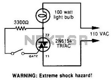
A triac can be utilized as a line-operated AC power switch that directly controls lamps, heaters, or motors. A brief current pulse into the gate activates the triac, and it remains on until the main current reverses. A triac, or...
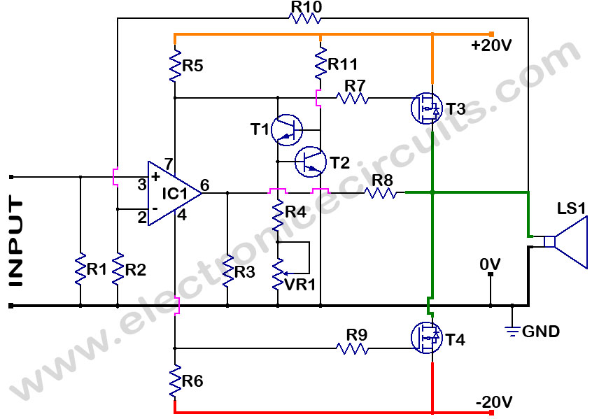
MOSFET Power Amplifier Circuit diagrams. Two complementary MOSFETs are used to deliver 20W into 8Ω. The described MOSFET power amplifier circuit utilizes two complementary MOSFETs, which are arranged in a push-pull configuration to efficiently amplify audio signals. The circuit is...