
Computer Microphone Circuit

The circuit design involves a composite amplifier configuration that effectively enhances the performance of an electret microphone when interfacing with a PC sound card. The primary component, the BC413B transistor, is configured in a common emitter arrangement, which is known for its ability to amplify weak signals. This configuration increases the voltage gain, allowing the low-level audio signal from the electret microphone to be boosted sufficiently for processing by the sound card.
Following the amplification stage, the BC547C transistor is employed as an emitter follower. This configuration is crucial for impedance matching; it provides a high input impedance while maintaining a low output impedance. This characteristic is particularly beneficial when the microphone and associated circuitry are situated away from the sound card, as it minimizes signal degradation over longer distances. The low output impedance also facilitates the use of shielded cables, which further reduces susceptibility to electromagnetic interference and ensures a clean, high-quality audio signal.
Overall, this circuit design exemplifies a practical approach to integrating an electret microphone with a PC sound card, enhancing audio capture capabilities while maintaining signal integrity. The careful selection of components and their configuration addresses common challenges in audio signal processing, making it a valuable addition to audio-related projects.This circuit was submitted and design by Lazar Pancic from Yugoslavia. The sound card for a PC generally has a microphone input, speaker output and sometimes line inputs and outputs. The mic input is designed for dynamic microphones only in impedance range of 200 to 600 ohms. Lazar has adapted the sound card to use a common electret microphone usi ng this circuit. He has made a composite amplifier using two transistors. This is the figure of the circuit. This is the explanation about the principle work of the circuit. The BC413B operates in common emitter to give a slight boost to the mic signal. This is followed by an emitter follower stage using the BC547C. This is necessary as the mic and circuit and battery will be some distance from the sound card, the low output impedance of the circuit and screened cable ensuring a clean signal with minimum noise pickup. 🔗 External reference
Related Circuits
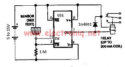
The water sensor circuit utilizes a 555 timer circuit along with common electronic components. It consists of two metal electrodes positioned closely enough that a drop of water can create a conductive bridge between them. If the water is...
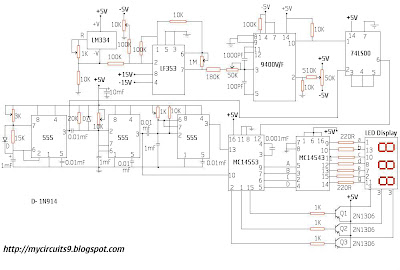
This circuit consists of a temperature sensor, amplifier, voltage-to-frequency (V/F) converter, a three-digit binary coded decimal (BCD) counter, a time base, and seven-segment LED displays. In addition to the 9400 V/F converter, other integrated circuits (ICs) required for this...
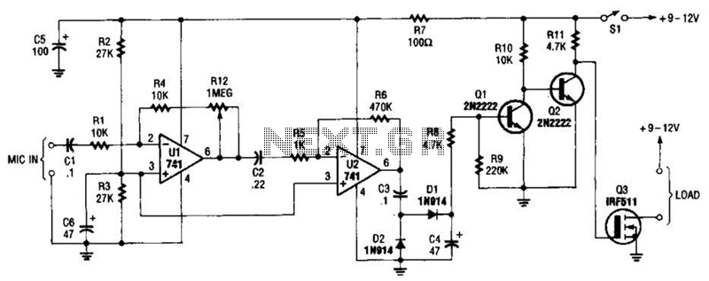
The audio-controlled switch utilizes a pair of 741 operational amplifiers, two 2N2222 general-purpose transistors, a hexFET, and several supporting components to create a circuit capable of activating devices such as a tape recorder, a transmitter, or virtually any other...
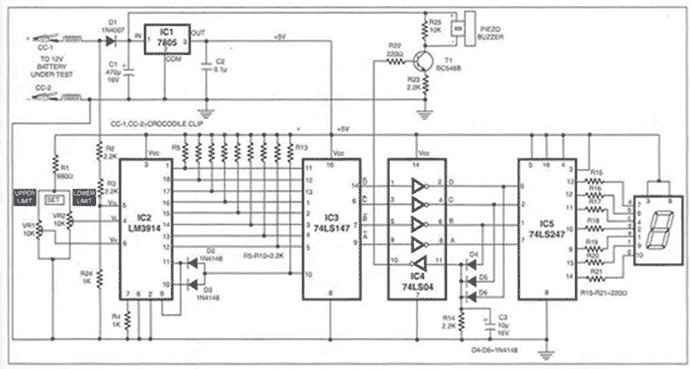
A battery is a crucial component of any battery-backed system. Often, the battery is more costly than the system it supports. Therefore, it is essential to implement all practical measures to extend battery life. According to manufacturer data sheets,...
Short circuits in the tracks, points, or wiring are almost inevitable when building or operating a model railway. Although transformers for model systems must be protected against short circuits by built-in bimetallic switches, the response time of such switches...
Logic testers are simple yet very useful devices for testing digital circuits. A logic probe can be designed in various ways. Logic testers, commonly referred to as logic probes, are essential tools in the field of digital electronics. These...