
phone charger using a 7805 voltage regualtor

The 7805 voltage regulator is a popular component used in various electronic circuits to provide a stable output voltage of 5V. In this charging circuit, the 7805 is employed to convert a higher input voltage, typically from a power source like a USB charger or a battery, to the required 5V output suitable for charging smartphones.
The circuit typically includes the following components:
1. **Input Power Source**: This can be a USB power supply or a battery that provides a voltage higher than 5V, usually in the range of 7V to 12V.
2. **7805 Voltage Regulator**: This three-terminal device regulates the input voltage down to a stable 5V output. It has an input terminal, an output terminal, and a ground terminal.
3. **Capacitors**: To ensure stability and reduce noise in the output voltage, input and output capacitors are often added. A common configuration uses a 0.33µF capacitor at the input and a 0.1µF capacitor at the output.
4. **Diode (optional)**: A diode may be placed in parallel with the input to protect against reverse polarity connections, which can damage the circuit.
5. **Charging Circuitry**: Depending on the smartphone's charging requirements, additional components such as a microcontroller or charging IC may be included to manage the charging process, monitor battery status, and ensure safe charging rates.
The layout of the circuit should be designed to minimize noise and interference, with careful attention to the placement of components to avoid inductive coupling. The heat dissipation of the 7805 should also be considered, as it can generate heat during operation, especially when the input voltage is significantly higher than the output voltage. A heat sink may be necessary to prevent overheating and ensure reliable operation.
Overall, this simple 7805 charging circuit is effective for recharging smartphones and can be implemented in various portable electronic projects.Simple 7805 charging circuit to recharge smart phones like the Incredible. Similar in design to the Minty Boost.. 🔗 External reference
Related Circuits
This simple circuit makes it possible to monitor the charging process to a higher level. If you need more information then check out the LM3914 Datasheet. Final adjustments are simple and the only thing needed is a digital voltmeter...
This schematic illustrates a simple DIY solar cell phone or USB charger circuit. It is designed to charge any device that can be powered from a computer USB port, such as MP3 players, cell phones, and iPhones. The circuit...
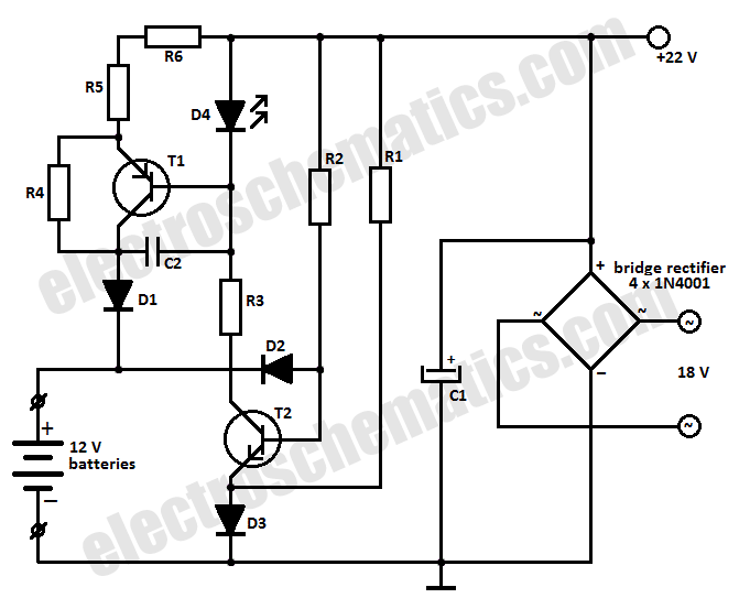
This battery charger circuit is designed to charge one or more batteries with a total nominal voltage of 12 V, which accommodates either ten NiCd batteries or six 2 V lead-acid batteries. The battery charger circuit operates by utilizing a...
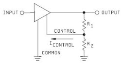
Neither term describes a regulator, only its placement within a circuit or system. Any voltage regulator could meet the requirements, depending on its placement. A listing of Analog Voltage Regulator IC manufacturers. The types of products or devices they...
This circuit is designed to drive a total of 42 LEDs, assuming a forward voltage of approximately 2.2V per LED and a forward current of around 21mA for adequate brightness. If the specifications of the LEDs differ significantly, modifications...
The 2N3819 is an n-channel JFET specifically designed for RF and mixer applications, offering very low noise, minimal distortion, and excellent high-frequency gain. Creating a PCB can be accomplished in a few straightforward steps. Begin by using PCB design...