
12V Battery Charger Circuit

The battery charger circuit operates by utilizing a voltage regulator and a suitable charging algorithm to ensure safe and efficient charging of the batteries. The circuit typically consists of a transformer, rectifier, filter capacitor, and a voltage regulator, which together convert the AC mains voltage to a stable DC output suitable for battery charging.
In a standard configuration, the transformer steps down the AC voltage to a lower level, which is then rectified by a diode bridge to convert the AC voltage to pulsating DC. A filter capacitor smooths out the rectified voltage, providing a more stable DC output. The voltage regulator, often a linear regulator or a switching regulator, maintains the output voltage at the desired level, compensating for variations in input voltage and load conditions.
For charging NiCd batteries, the circuit may include additional features such as a constant current source to prevent overcharging and a temperature sensor to monitor battery temperature during the charging process. This ensures that the batteries are charged safely and efficiently without the risk of thermal runaway or damage.
When charging lead-acid batteries, the circuit may incorporate a multi-stage charging process, including bulk charging, absorption charging, and float charging phases. This method helps to optimize the charging process, prolong battery life, and enhance performance.
In summary, this battery charger circuit is versatile and can accommodate various battery types, making it suitable for applications requiring reliable battery charging solutions. Proper design considerations and components selection are crucial for ensuring the circuit's efficiency and safety during operation.This battery charger circuit can be used to charge one or more batteries with the total nominal voltage of 12 V, meaning ten NiCd battery or six 2 V lead a.. 🔗 External reference
Related Circuits
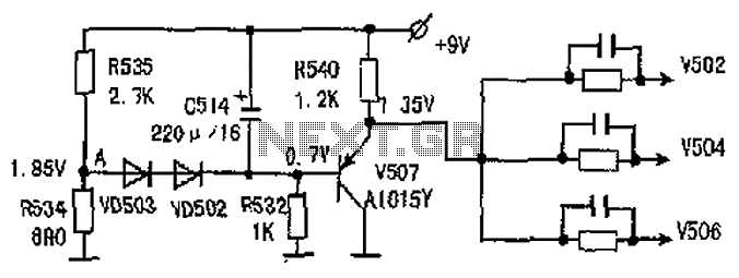
The common-emitter amplifier circuit V502, V504, V506 is designed to generate a static potential bias voltage through an emitter follower configuration, as illustrated in Figure 3. The active filter is formed by components V507, VD502, and VD503. The emitter...
This simple circuit tests speakers, microphones, transformers, and voltage. It is essentially a very low-frequency oscillator that produces extremely short pulses. The sound produced is easy to hear and helps determine the precise direction it originates from, making it...
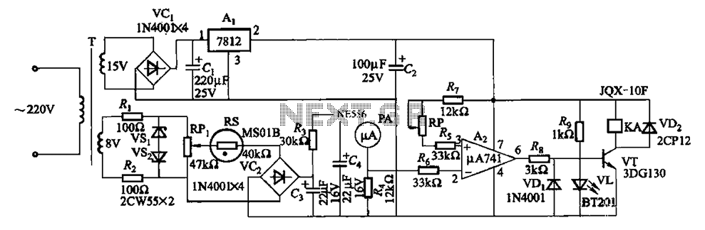
The humidity alarm system is based on integrated circuits and relays, utilizing the pA741 circuit. The MS01 employs a wet-type humidity resistance element as a probe. When the humidity exceeds a predetermined value, specifically set at 6 feet high,...
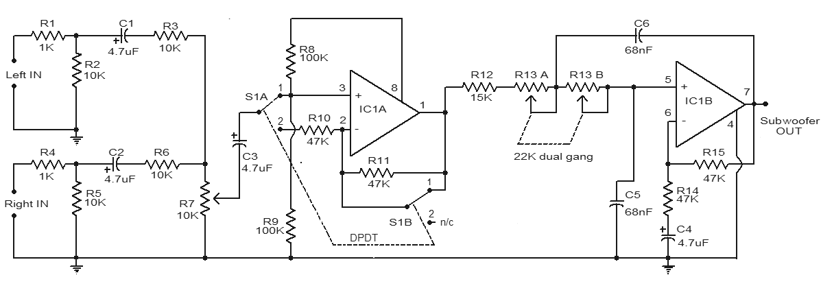
This is a simple subwoofer filter circuit that can be powered by a 12V DC source. It is particularly useful in automotive applications for subwoofers. The circuit functions as a low-pass filter, with a pass frequency adjustable between 60...
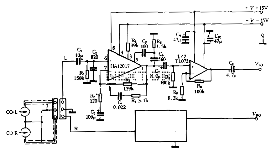
Figure 3-16 illustrates a low-noise preamplifier equalizing circuit using the HA12017. This circuit includes playback components R3, R4, and C4, which conform to a standard balanced network. The gain of the circuit is -7dB at 1kHz, while the output...
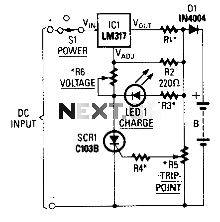
When power is applied to the circuit, SCR1 is off, resulting in no bias current path to ground; thus, LM317 operates as a current regulator. The LM317 is connected to the battery through steering diode D1, limiting resistor R1,...