
Phono Preamplifier

Expanding on this, the circuit's efficiency is largely due to its simple design, which includes a phono preamplifier that is adept at handling the demands of older vinyl records. The moving-magnet cartridges, which are a popular choice due to their affordability, contribute to the overall effectiveness of the circuit. This is particularly true when the circuit is used in conjunction with audio power amplifiers, as the description suggests.
The low noise characteristic of the circuit ensures a clean, clear audio output, free from unwanted interference. This is complemented by the accurate RIAA frequency response curve which ensures a faithful reproduction of the audio signal across the full range of audible frequencies. Moreover, the minimal distortion characteristic of the circuit ensures that the audio output remains true to the original recording, without any unwanted alterations or colorations.
The circuit's strong performance in handling high frequency transients, due to the passive equalization in the 1 to 20KHz range, is a key factor in its ability to deliver a high-quality audio output. This ensures that the audio signal remains stable and consistent, even when dealing with complex or demanding audio material.
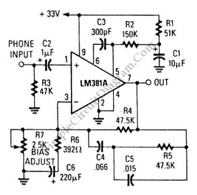
The final element of the circuit, the transistors and associated components, provide a ± 18V supply to the op-amp. This not only improves the headroom, allowing for greater dynamic range in the audio signal, but also enhances the maximum output voltage, ensuring that the circuit can deliver a powerful audio output when required.In recent years, following CD`s introduction, vinyl recordings are almost disappeared. Nevertheless, a phone preamplifier is still useful for listening old vinyl discs from a well preserved collection. This simple but efficient circuit devised for cheap moving-magnet cartridges, can be used in connection with both audio power amplifiers shown in preceding pages, featuring low noise, good RIAA frequency response curve, low distortion and good high frequency transients behavior due to passive equalization in the 1 to 20KHz range.
Transistors and associated components provide ± 18V supply to the op-amp, improving headroom and maximum output voltage. 🔗 External reference
Related Circuits
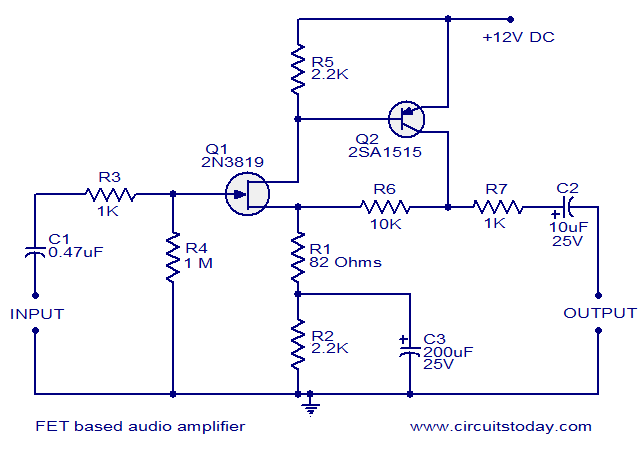
This circuit is a low-noise audio preamplifier that utilizes one FET and one BJT. The audio signal to be amplified is connected to the base of FET Q1 through capacitor C1 and resistor R3. The base of transistor Q2...

Part of the challenge is that multiple capacitors and resistors are present in the RIAA circuit. This is derived from the Harman-Kardon schematic. The information for the Citation IV is not readily available, but it is simpler to replace...
This circuit is an ultra-low noise magnetic phono preamplifier. It utilizes an LM381/1A operational amplifier and incorporates RIAA equalization. The ultra-low noise magnetic phono preamplifier is designed to amplify the weak audio signals produced by magnetic phono cartridges while...
The circuit diagram of a guitar preamplifier is designed to accept any standard guitar pickup and features two signal outputs. A typical example of a pickup attached to a guitar headstock is illustrated. The pickup device consists of a...
The circuit design utilizes a VHF amplifier configured to operate within the frequency range of 88 to 108 MHz, specifically for Band 2 radio applications. The VHF amplifier circuit is designed to enhance weak radio frequency signals in the specified...
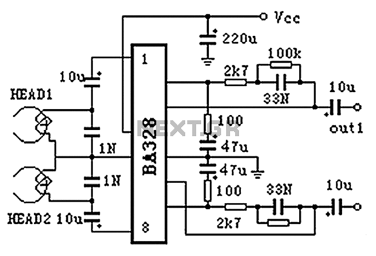
The BA328 is a dual preamplifier circuit designed with minimal external components, facilitating straightforward installation within a single 8-pin DIP package. The circuit features a wide operating voltage range, low noise levels, and high open-loop gain, ensuring good balance...