
Electric Guitar Preamplifier
The guitar preamplifier circuit serves as a crucial interface between passive guitar pickups and active amplification systems, ensuring that the delicate signal from the instrument is preserved and enhanced. The choice of a common-emitter amplifier configuration allows for a significant voltage gain while maintaining a high input impedance, which is essential for interfacing with high-impedance pickups. The degenerative feedback implemented in the emitter helps to stabilize the gain and reduce distortion, providing a cleaner output signal.
The use of the TL071 op-amp is particularly advantageous due to its low noise characteristics and high input impedance, making it suitable for audio applications. The gain adjustment via VR2 allows for flexibility in tailoring the output level to match the requirements of different amplifiers or mixers. The inclusion of both master and slave outputs enhances the circuit's versatility, allowing simultaneous connection to multiple devices without signal degradation.
Grounding the metallic enclosure is a critical step in minimizing electromagnetic interference and ensuring optimal performance. The design's power supply requirements highlight the importance of stable voltage levels in audio circuits, as fluctuations can lead to undesirable noise and distortion. The option to use a battery provides portability, making this preamplifier suitable for live performances where access to mains power may be limited.
Overall, this guitar preamplifier circuit is an effective solution for musicians seeking to achieve high-quality sound reproduction from their instruments, with considerations for both performance and practicality.Here is the circuit diagram of a guitar preamplifier that would accept any standard guitar pickup. It is also versatile in that it has two signal outputs. A typical example of using a pick-up attached to a guitar headstock is shown in Fig. 1. The pickup device has a transducer on one end and a jack on the other end. The jack can be plugged into a preamplifier circuit and then to a power amplifier system. The pickup device captures mechanical vibrations, usually from stringed instruments such as guitar or violin, and converts them into an electrical signal, which can then be amplified by an audio amplifier. It is most often mounted on the body of the instrument, but can also be attached to the bridge, neck, pick-guard or headstock.
The first part of this preamplifier circuit shown in Fig. 2 is a single-transistor common-emitter amplifier with degenerative feedback in the emitter and a boot-strapped bias divider to secure optimal input impedance. With the component values shown here, the input impedance is above 50 kilo-ohms and the peak output voltage is about 2V RMS.
Master-level-control potentiometer VR1 should be adjusted for minimal distortion. The input from guitar pickup is fed to this preamplifier at J1 terminal. The signal is buffered and processed by the op-amp circuit wired around IC TL071 (IC1). Set the gain using preset VR2. The circuit has a master and a slave control. RCA socket J2 is the master signal output socket and socket J3 is the slave. It is much better to take the signal from J2 as the input to the power amplifier system or sound mixer. Output signals from J3 can be used to drive a standard headphone amplifier. Using potentiometer VR3, set the slave output signal level at J3. House the circuit in a metallic case. VR1 and VR3 should preferably be the types with metal enclosures. To prevent hum, ground the case and the enclosures. A well-regulated 9V DC power supply is crucial for this circuit. However, a standard 9V alkaline manganese battery can also be used to power the circuit. Switch S1 is a power on/off switch. 🔗 External reference
Related Circuits
Using a magnetic compass, ensure that both pickups have a South polarity on the top of each pickup. Verify this by checking for a North polarity on the bottom of the pickups. It is uncommon to find both pickups...
The objective of this design is to create a Combo amplifier that is reminiscent of those commonly found in the 1960s and 1970s. It is particularly effective as a guitar amplifier but is also suitable for various electronic musical...
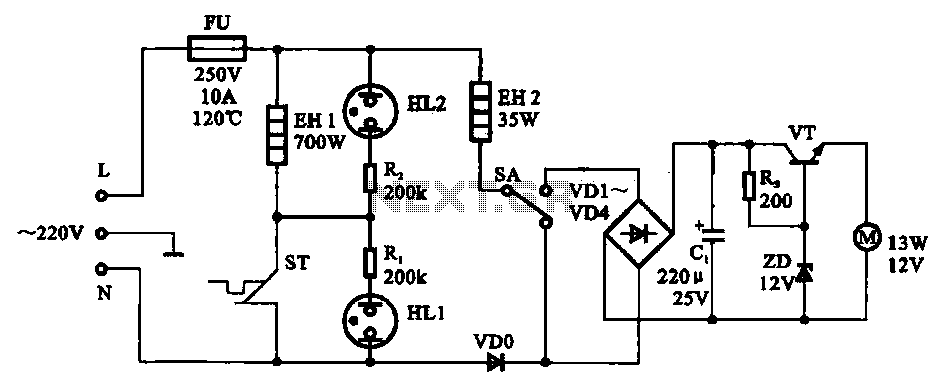
The electric thermos temperature detection control circuit is designed to monitor and manage the temperature within an electric thermos. It primarily consists of a control circuit for the boiler heater and heater insulation, an electrical magnetic pump motor drive...
High-quality, discrete component design for input and tone control modules to complement the 60-watt MOSFET audio amplifier with a high-quality preamplifier design. The circuit design focuses on creating a high-fidelity audio preamplifier that enhances the performance of a 60-watt MOSFET...
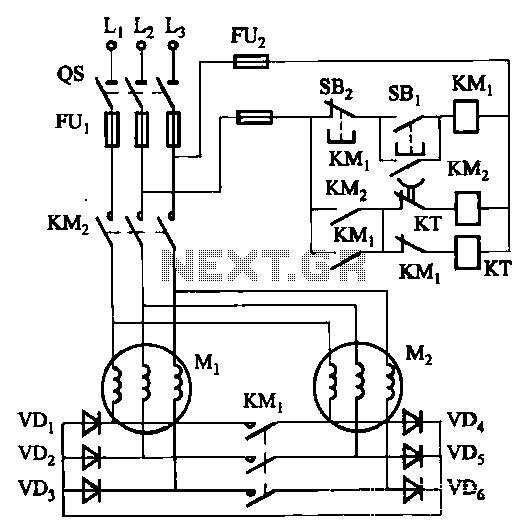
The circuit depicted in Figure 3-157 is designed for motors with a capacity of no more than 11 kW, requiring precise stopping capabilities. Upon shutdown, contact KMi releases, and the motor stator windings are configured into a three-phase rectifier...
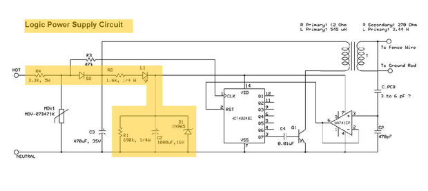
This electric fencing solution is essential for operation in regions with dry ground. It includes a schematic for an Electric Fence Charger, originally created by KC Mylrea in 1972. The purpose of this system is to power electric fences...