
Photo Switch Circuit

The circuit utilizes the NE555 timer IC configured in a comparator mode. The primary function of this circuit is to detect changes in ambient light levels and control a relay accordingly. The NE555 is a versatile integrated circuit capable of operating in various modes, and in this configuration, it serves as a light-dependent switch.
The circuit includes a light-dependent resistor (LDR), which changes its resistance based on the light intensity. When the light level falls below a predetermined threshold, the resistance of the LDR increases, causing the voltage at the non-inverting input of the NE555 to rise. This change in voltage triggers the output of the NE555, which activates the relay.
The relay acts as a switch that can control higher power devices, making the circuit practical for applications such as automatic lighting systems, security systems, or industrial automation. Additional components may include resistors to set the threshold levels, a potentiometer for fine-tuning sensitivity, and a capacitor to stabilize the circuit.
The schematic diagram typically illustrates the connections of the NE555, LDR, resistors, and relay, providing a clear visual representation of the circuit's functionality. This design is relatively straightforward, making it accessible for hobbyists and professionals alike who are looking to implement light-sensitive switching in their projects.A simple photo switch circuit using NE 555 IC with diagram and schematic.This photo switch ons a relay when light intensity crosses limit.A light sensor circuit for home and industrial purpose.. 🔗 External reference
Related Circuits

The 20-W + 20-W stereo amplifier consists of two complete, separate 20-W RMS bridge-type amplifiers. The input signal source is brought into the amplifier through a voltage divider network, which is composed of resistors R1, R2, and potentiometer P1....

A voltage supply ranging from 6 V to 15 V is required when using a single LED per module. An increase in the number of LEDs necessitates a corresponding increase in the voltage supply, with additional LEDs connected in...
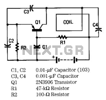
The metal locator utilizes a one-transistor oscillator in conjunction with an AM radio to detect metal. Transistor Q1 is a PNP transistor connected to the oscillator circuit. Resistor R1 supplies the appropriate base bias, while capacitors C3 and C4,...
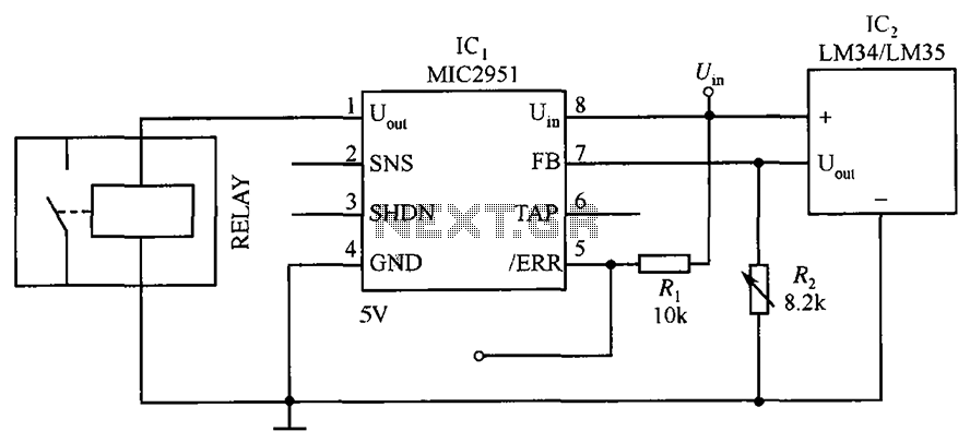
The circuit depicted in the figure utilizes a thermal protection system featuring the MIC2951 component. The temperature threshold can be adjusted by modifying resistor R2. The thermal protection circuit employing the MIC2951 is designed to monitor and regulate temperature within...

Accurate 50Hz Oscillator Circuit Using 555 and 7490. This circuit generates a 50Hz pulse. It consists of a 555 timer and two 7490 divide-by-ten counters. The circuit utilizes a 555 timer configured in astable mode to produce a square wave...

This is a variable power supply controlled by a PIC microcontroller. An LCD display is included in the circuit to show the actual output voltage and current values. A push-button switch is used to adjust the output voltage and...