
Overheat protection system consisting of circuit diagram MIC2951

The thermal protection circuit employing the MIC2951 is designed to monitor and regulate temperature within a specified range. The MIC2951 is a low-dropout voltage regulator that can be configured to provide a stable output voltage while also incorporating thermal protection features.
In this circuit, the key component is the MIC2951, which operates by comparing the output voltage to a reference voltage. When the temperature exceeds the set threshold, determined by the value of resistor R2, the circuit activates a protective mechanism. This can involve cutting off power to the load or triggering an alarm system to indicate an over-temperature condition.
The adjustment of R2 allows for flexibility in setting the desired temperature threshold. By changing the resistance value, the temperature at which the circuit activates can be fine-tuned to suit specific applications. This feature is particularly useful in environments where temperature fluctuations may occur, ensuring that sensitive electronic components are safeguarded against overheating.
Additional components that may be included in the schematic could consist of capacitors for stability, diodes for reverse polarity protection, and transistors for switching applications. The layout of the circuit should ensure minimal interference and optimal thermal management to enhance the performance of the MIC2951 and improve the overall reliability of the thermal protection system. Circuit shown in Figure is the use of thermal protection system consisting of circuit MIC2951. The circuit is set by adjusting the temperature threshold R2.
Related Circuits

The CA3189E is a comprehensive FM-IF system designed for high fidelity FM tuners. It includes a three stage FM-IF amplifier/limiter configuration with level detectors for each stage, a double-balanced quadrature FM detector and an audio amplifier that features the...
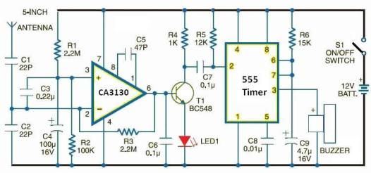
This electronic schematic can be used to design a simple cellular phone detector circuit capable of sensing the presence of an activated mobile phone from a distance of approximately 1.5 meters. The C3 capacitor should have lead lengths of...

Bidirectional thyristor control manages the trigger voltage output from the step-down transformer at 12V when the water activates the electrodes. It is part of a drawable circuit that regulates the level. The circuit includes a current-limiting resistor (Ri) to...
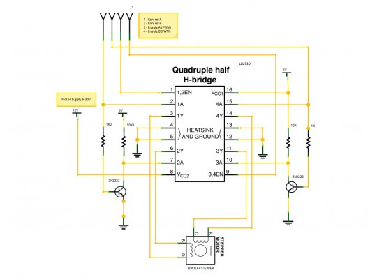
A stepper motor controller based on schematics available on the Arduino website. Initially, a two-pin configuration was attempted for a bipolar stepper motor, but it did not function as expected, especially with the library provided on the site. The...
The 5W/6V solar panel can achieve a maximum current of approximately 500 to 800mA, peaking at 800mA during noon. Limiting the current to 150mA appears inefficient. A 1W panel can supply around 160mA during peak performance for up to...
This FM RF power amplifier circuit is constructed using a BLY94 transistor, which can deliver up to 50W at a frequency of 175MHz with a power gain of 7dB, resulting in approximately 5 times power amplification. However, in this...