
Photo Timer Circuit

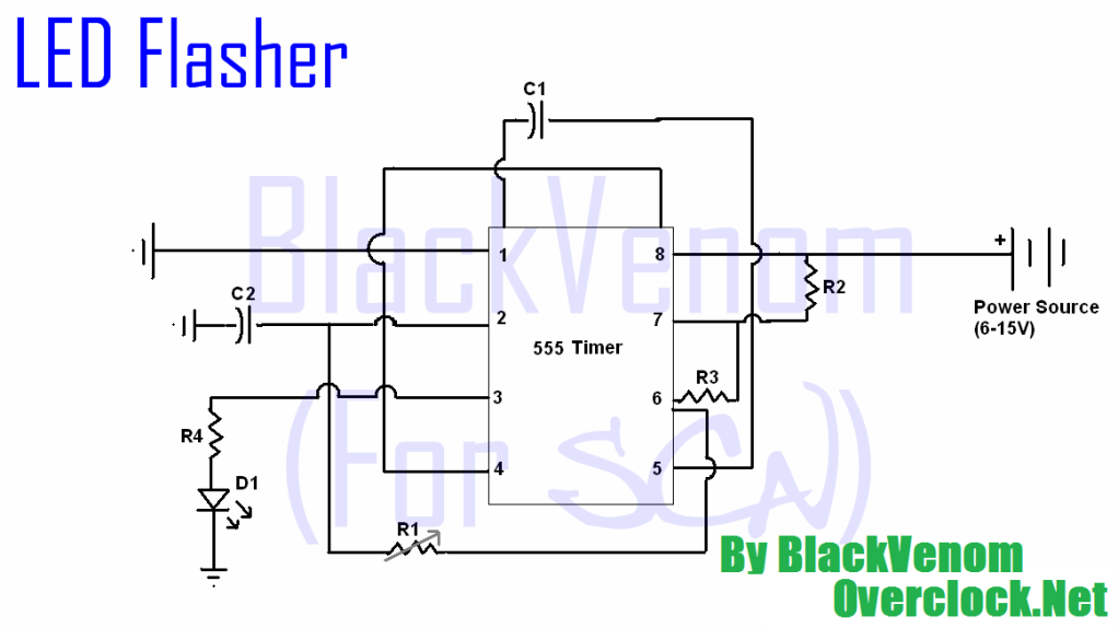
The circuit utilizes a timing mechanism controlled by a potentiometer (R2) and a timing capacitor (C1). The potentiometer allows for adjustable resistance, which in turn modifies the charge time of the capacitor. The capacitor C1, rated at 100 µF, plays a crucial role in determining the timing interval; as it charges through R2, the voltage across C1 rises. This voltage is monitored at pin 3 of the integrated circuit (IC), which is configured as a timer or oscillator.
When the voltage across C1 reaches a specific threshold, the output at pin 3 transitions from a low state to a high state. This change in output state is what activates the relay. In its default condition, the output remains low, ensuring that the relay remains deactivated. The range of timing from 1 second to 100 seconds is achieved by adjusting the resistance of the potentiometer R2. A lower resistance results in a faster charge time for C1, thus shortening the timing interval, while a higher resistance increases the charge time, extending the timing interval.
This circuit is typically employed in applications requiring timed control, such as in delay timers, automatic lighting systems, or any scenario where a relay needs to be controlled based on a timed event. Proper selection of R2 and C1 is critical, as it directly influences the timing accuracy and stability of the circuit. Additionally, care must be taken to ensure that the relay's specifications match the output capabilities of the IC to prevent any potential damage or malfunction.Time is set by potentiometer R2 which provides a range or 1 sec. To 100 seconds with timing capacitor C1 of 100uF. The output at pin 3 is normally low and the relay is held off.. 🔗 External reference
Related Circuits
All of the components in this list are generally available through RadioShack for less than $20. It is highly recommended to use a breadboard for assembly, as mistakes are common for first-time builders, and soldering can complicate troubleshooting. This...
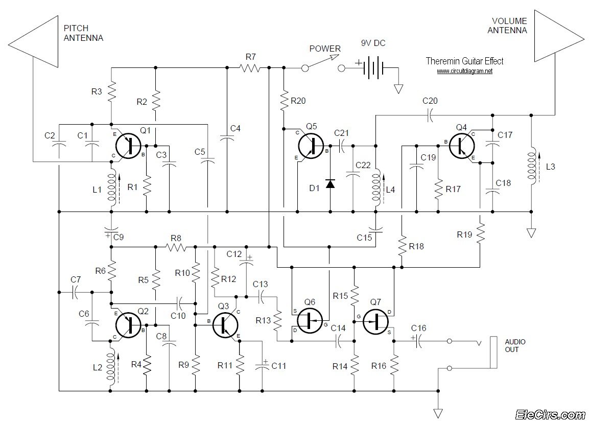
Below is the circuit diagram for the Theremin music instrument effect. A guitar or instrument amplifier is an ideal companion for the Theremin, allowing for bass or treble boost as desired, as well as fuzz (distortion) or reverberation if...
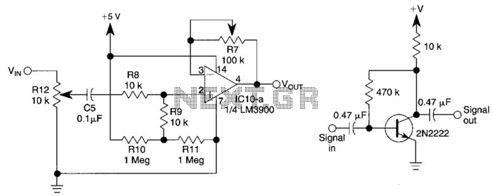
This circuit utilizes one-quarter of an LM3900 to create a simple variable-gain front end for an oscilloscope. R7 serves as the gain control. Additionally, a basic preamplifier is included for applications requiring more than 10X gain. The circuit employs the...
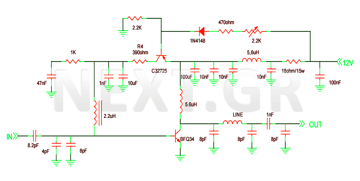
This project involves the construction of a VHF-UHF linear amplifier capable of operating at frequencies ranging from 47 MHz to 740 MHz. It serves as the final output stage for any transmitter functioning within these frequencies. The amplifier utilizes...

At the input of the operational amplifier, a resistor-diode network can be constructed to create a square-law function conversion circuit. This resistor-diode network acts as a voltage divider, where the input voltage variations lead to different partial pressures. The...
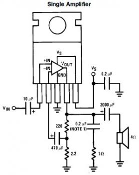
This is a simple mini audio amplifier circuit built around a single LM383 integrated circuit, along with several discrete components to support its operation. The circuit is capable of delivering approximately 7W of audio output. It can be constructed...