
Variable Gain Amplifier Circuit

The circuit employs the LM3900, a quad operational amplifier, configured in a non-inverting amplifier setup to achieve variable gain. The gain control resistor, R7, is strategically placed in the feedback loop of the op-amp to allow for adjustment of the gain from unity up to a specified maximum, which can exceed 10X. This feature is particularly beneficial for oscilloscope applications where signal amplification is necessary to visualize low-level signals effectively.
In the schematic, the input signal is fed into the non-inverting terminal of the op-amp. The gain can be adjusted by changing the value of R7; as R7 decreases, the gain increases, allowing for a flexible response to varying input signal levels. The output of the op-amp is then connected to the oscilloscope input, enabling the user to observe the amplified signal.
The preamplifier section, which is also part of the circuit, enhances the input signal before it reaches the variable gain stage. This preamplifier can be implemented using another section of the LM3900, ensuring that even very weak signals can be adequately amplified to a level suitable for further processing. The design considerations for the preamplifier include low noise and high input impedance to avoid loading the signal source.
Overall, this circuit design is efficient for applications requiring adjustable gain and is particularly suited for use in laboratory settings or in equipment where signal integrity and flexibility are paramount. This circuit uses 1/4 of an LM3900 to build a simple variable-gain front end for an oscilloscope. R7 is the gain control. Also shown is a simple preamp if you need more than 10X of gain.
Related Circuits
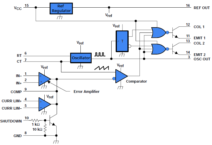
This document outlines a simple PWM (Pulse Width Modulation) DC to AC voltage inverter circuit based on the SG3524 integrated circuit. The SG3524 is a fixed frequency PWM voltage regulator control circuit that offers indifferent outputs suitable for both...

This circuit for a laser door alarm operates on the principle of laser beam interruption. A low-cost laser pointer serves as the light source. When an object disrupts the laser beam, an alarm is triggered for a few seconds....
A Variable DC Power Supply is one of the most useful tools on the electronics hobbyist's workbench. This circuit is not an absolute novelty, but it is simple, reliable, rugged, and short-proof, featuring variable voltage up to 24V and...

The sound produced imitates the rise and fall of an American police siren. When first switched on, the 10 µF capacitor is discharged, and both transistors are off. When the push button switch is pressed, the 10 µF capacitor...
This article presents a driver circuit for a 12V, 5W fluorescent lamp. The circuit utilizes a standard 220V to 10V step-down transformer operated in reverse to achieve a 12V output. The driver circuit for a 12V, 5W fluorescent lamp is...
This page features H-Bridge circuits used for controlling direct current motors. Several designs are shown using both CMOS and Bi-Polar power devices. These circuits could be used as the basis for Model Railroad DCC Boosters or PWM motor controllers....