
Photoresistor LDR light control switch circuit diagram

The circuit utilizes a photoresistor (Light Dependent Resistor, LDR) as the primary sensor for detecting ambient light levels. The LDR exhibits a significant change in resistance based on the intensity of light falling on it; typically, its resistance decreases in bright light and increases in darkness. This property is crucial for the operation of the circuit, as it determines the behavior of the connected transistor.
In this configuration, the LDR is connected to the base of a standard bipolar junction transistor (BJT) with a gain factor (h_FE) of approximately 100. This transistor acts as a switch or amplifier, enabling the control of output signals based on the input from the LDR. When the LDR is exposed to light, its resistance drops, allowing current to flow into the base of the transistor, which in turn allows a larger current to flow from the collector to the emitter, effectively turning the transistor "on." Conversely, in low light conditions, the resistance of the LDR increases, reducing the base current and turning the transistor "off."
For applications requiring the control of higher power loads, such as motors or lamps, it is advisable to employ a Darlington pair configuration. A Darlington transistor consists of two BJTs connected in such a way that the current amplified by the first transistor is further amplified by the second. This configuration provides a much higher current gain, making it suitable for switching larger loads without requiring significant input current, thus enhancing the circuit's efficiency and reliability.
In summary, the circuit effectively utilizes an LDR to control a transistor's state based on light intensity, with the option to scale the design for higher power applications through the use of Darlington transistors, ensuring versatility and adaptability in various electronic applications. As shown in the circuit, there is the incident at the time, this circuit is connected with photoresistor LDR transistor is turned high or zero level. Amplification factor of tr ansistor B 100 is sufficient, the photosensitive resistor between 100 ~ 100k Europe, corresponding to the case when the light irradiation and dark. If you want to control high power loads should be used Darlington transistors.
Related Circuits
The circuit below illustrates the use of the LM741 integrated circuit (IC) in a light and dark sensor configuration. This circuit offers several features, including a 1 Watt LED spotlight, making it suitable for a wide range of renewable...
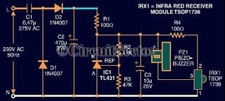
This document presents an infrared remote control tester circuit that can be constructed at a low cost. The circuit is built around the infrared receiver module TSOP1738. The state of the remote control can be observed through the sound...
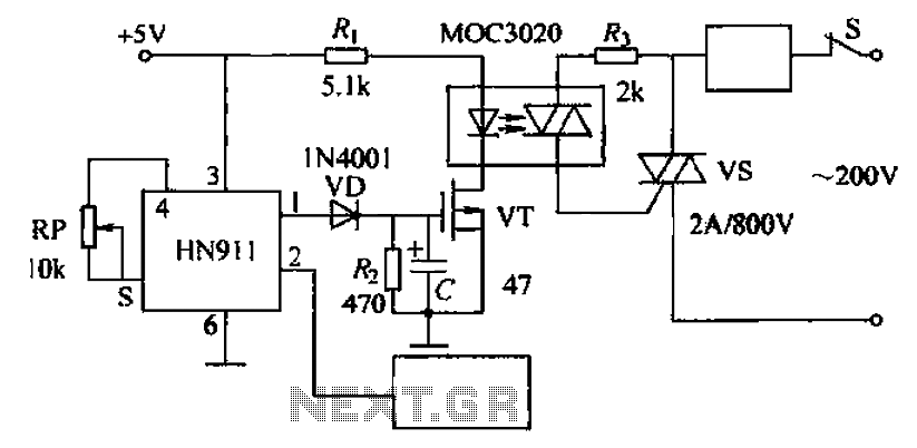
Automatic door control circuit diagram. It utilizes a pyroelectric infrared detection module, HN911, for human motion detection. A variable resistor (potentiometer) is used to adjust the delay time controlled by a transistor (VT). An optocoupler (MX: 3020) provides AC...
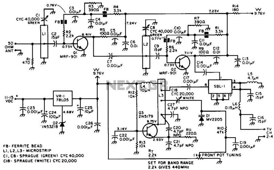
Most ATV (Amateur Television) transmitters operate using a Double Sideband (DSB) signal, while commercial television stations utilize a Vestigial Sideband (VSB) signal. This distinction is leveraged in this converter to utilize the lower sideband, thereby reducing interference from repeaters...
This circuit functions as a camera switch, allowing multiple cameras to be connected to a single monitor. It can operate in both manual and automatic modes. In automatic mode, the circuit utilizes a 555 astable multivibrator to generate a...
A circuit designed to extract and measure the modulated carrier of an infrared remote control. This circuit amplifies the entire received signal, allowing the waveform to be displayed on an oscilloscope or a frequency counter. It can measure modulation...