
Pyroelectric automatic door control circuit

The automatic door control circuit leverages the HN911 pyroelectric infrared detection module to sense human presence through infrared radiation emitted by the human body. The HN911 module is sensitive to changes in infrared levels, which allows it to detect motion effectively. The output from the module is connected to a transistor (VT), which serves as a delay control mechanism. The delay is adjustable via a potentiometer, allowing for customization based on the specific application requirements.
The circuit design includes an optocoupler (MX: 3020) that provides electrical isolation between the control circuit and the load circuit. This isolation is crucial for protecting sensitive components from voltage spikes or noise that may occur in the load circuit, ensuring reliable operation.
In the absence of detected motion, the HN911's output remains low, resulting in no activation of the control signal from VT. Consequently, the triac (VS) remains off, and the electric load, which operates the door mechanism, is inactive, keeping the door closed.
Upon detecting motion, the HN911's output switches to high, which activates the thyristor (VT2). This action enables current to flow to the motor, which opens the automatic doors. The operation of the doors is monitored by a limit switch (S) that is triggered when the doors reach their fully open position, cutting off power to the motor and stopping further operation.
The design also incorporates a feedback mechanism for controlling door closure. The output from the HN911 can be utilized not only for opening the doors but also for signaling when to close them, enhancing the functionality of the automatic door system. This comprehensive approach ensures that the automatic door operates efficiently and safely in response to human presence. Automatic door control circuit diagram. Human motion detection using the new pyroelectric infrared detection module HN911. VT used as a delay control by adjusting potentiometer RP, can change the delay time control dummy. Optocoupler tuner MX: 3020 from AC and DC isolation. When no one walking time. HN911 output terminal O is low early. VT No control signal output, Triac vs closed, the load electric machine does not work, the door is closed. When someone approaching from the time gates. HN911 module detects infrared body radiation energy, the output terminal O is high, two-way goods thyristor VT2 conduction, load motor working, open the automatic doors.
When the automatic doors running in place, by the limit switch S off the power. Since HN911 output of block output level and the output of the opposite O level, it can be used the output terminal output control automatic door closed.
Related Circuits
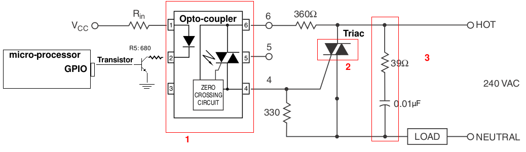
A light-dimming control system is being developed for a 240V heat lamp with a power dissipation of approximately 250W. The objective is to adjust the heat output of the lamp using control from a microprocessor. The development is based...
Originally posted by Pano: "Like putting milk and sugar in your coffee. Next time by, your Turkish coffee comes with no sugar, Dave." The provided text appears to be an informal comment comparing the addition of sugar and milk to...
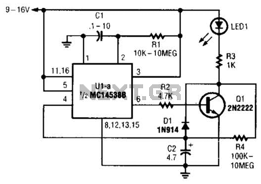
When power is first applied to the circuit, capacitor C2 begins to charge through LED1, resistor R3, and resistor R4. When the voltage across C2 reaches the input trigger level of operational amplifier U1, the output at pin 6...
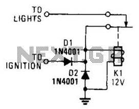
A relay and two diodes are all that is needed; the relay performs the job of a buzzer, so no annunciator is required. When the lights are left on while the ignition is off, the normally closed relay contacts...
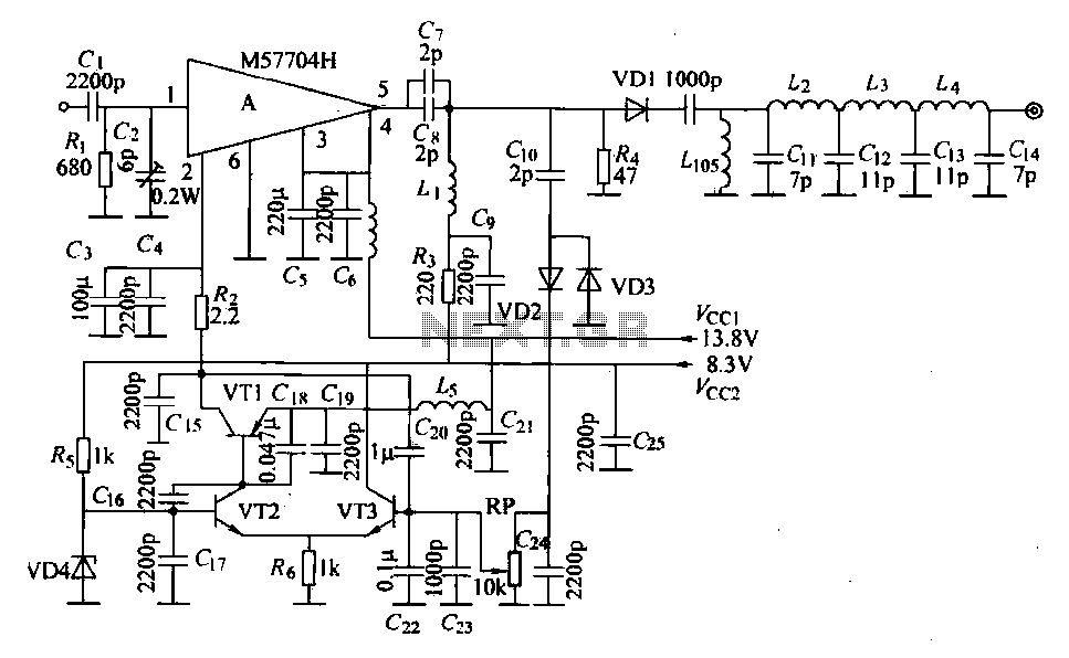
The FM radio transmitter is a high-frequency amplifier circuit that utilizes the Mitsubishi frequency set, specifically the M57704H discharge path. It operates within the frequency range of 457-458 MHz and has a transmission power of 5 watts. As illustrated...
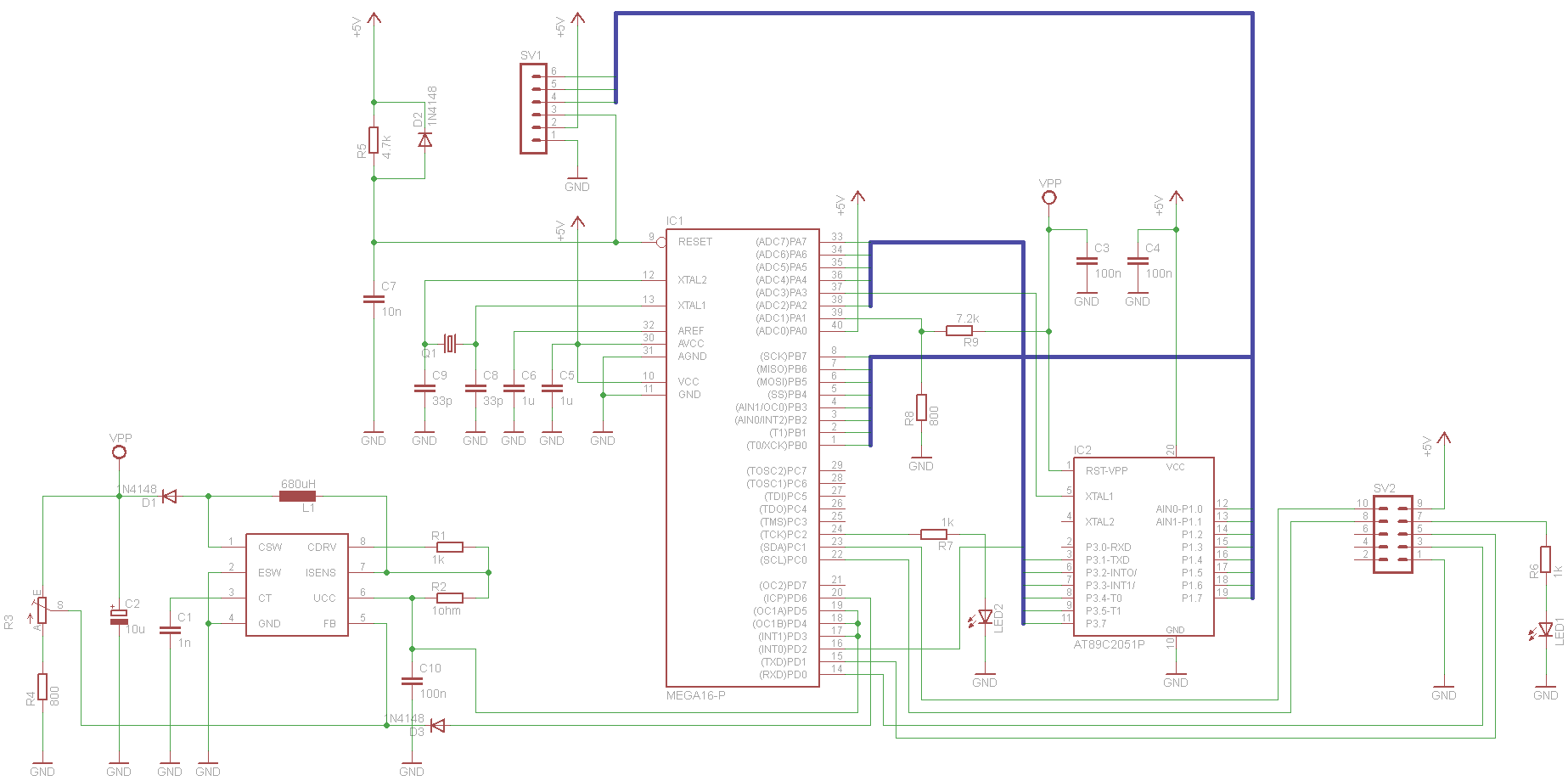
This project has been set aside for several years. It was initially intended for programming old 8051 microcontrollers, which have since become obsolete. The project was recently revisited due to the need for a programmer for the Atmel Xmega...