
pic 16f887 based digital thermometer

The circuit configuration for the DS1820 temperature sensor within a 1-Wire network is designed for simplicity and efficiency. The microcontroller serves as the central unit, managing communication and data collection from multiple DS1820 sensors connected to a single 1-Wire bus. Each DS1820 sensor is uniquely identified by its 64-bit ROM code, enabling the microcontroller to address each sensor individually, even when multiple sensors are connected in parallel.
In this configuration, the 1-Wire bus not only facilitates data communication but also provides power to the sensors, which allows for a reduction in wiring complexity. The bus operates on a master/slave architecture, where the microcontroller acts as the master device, sending commands and receiving data from the slave sensors. The 1-Wire protocol is efficient, requiring only a single data line for bi-directional communication, thus minimizing the number of pins required on the microcontroller.
The DS1820 sensor is capable of measuring a wide temperature range, making it suitable for various applications, from environmental monitoring to industrial temperature control. The sensor's accuracy of 0.5 °C ensures reliable readings for most applications. The One_Wire library, which contains predefined functions for interacting with the DS1820, simplifies the programming process, allowing users to easily implement temperature measurement without delving into complex protocol details.
In practice, the implementation involves initializing the One_Wire library, addressing each sensor using its unique ROM code, and executing commands to read temperature data. The microcontroller processes this data for further applications, such as logging, display, or control functions. Overall, the integration of multiple DS1820 sensors in a 1-Wire configuration represents an effective solution for temperature measurement in a variety of electronic projects.The hardware configuration when using multiple 1-Wire temperature sensors like the DS1820 is very simple, as illustrated in the block diagram below. A single-wire bus is used for communication between the microcontroller and the temperature sensor. It is also possible to power the devices direclty via this 1-Wire bus. An almost unlimited number of 1-WireTM devices can be connected to the bus because each device has a unique 64-bit ROM code identifier which is used to address each sensor. Temperature measurement is one of the most common tasks performed by the microcontroller. A DS1820 sensor is used for measurement here. It is capable of measuring temperature in the range of -55 °C to 125 °C with 0. 5 °C accuracy. For the purpose of transferring data to the microcontroller, a special type of serial communication called 1-wire is used.
Due to a simple and wide use of these sensors, commands used to run and control them are in the form of functions stored in the One_Wire library. There are three functions in total: Concretely, you don`t have to study documentation provided by the manufacturer in order to use this sensor.
It is sufficient to copy some of these functions in the program. 🔗 External reference
Related Circuits

In Figure 1, the host microprocessor (uP) manages the HMC6352 through I2C serial data interface lines designated for data (SDA) and clock (SCL). Two external 10k-ohm pull-up resistors connected to a nominal 3-volt DC supply establish normally high logic...
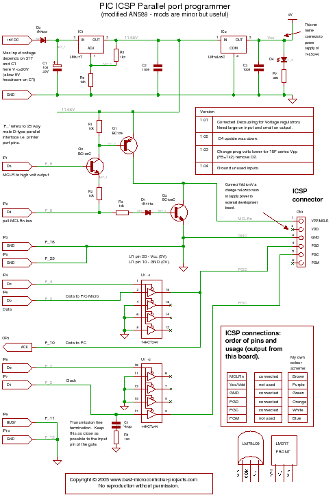
A PIC programmer circuit that operates using long cables from a PC to the programmer. The PIC programmer circuit is designed to facilitate the programming of PIC microcontrollers via a connection to a personal computer (PC) using extended cabling. This...

This circuit provides an intermittent siren output with an automatic reset feature. It can be operated manually through a key-switch or a hidden switch, and it can also be configured to activate automatically when the ignition is turned off....

Determining the identification of drive wires on a unipolar stepper motor, which is commonly found in surplus or salvaged equipment. The platform utilized is a PIC16F877A microcontroller programmed with BoostC, interfaced via RS232 to a PC running a terminal...

The ATtiny24 microcontroller's ADC is utilized to record an AC signal, which operates within a voltage range of 0 to 3.3V. A precision rectifier is employed to eliminate the negative portion of the signal. The circuit incorporates an LMC6484...

The following circuit illustrates a Touch Switch Circuit Diagram. This circuit is based on the CD4011 IC. Features include R1 and R2, which are the logic gates of the circuit. The Touch Switch Circuit utilizes the CD4011 integrated circuit, which...