
Touch SwitchCircuit Based On The CD4011 IC

The Touch Switch Circuit utilizes the CD4011 integrated circuit, which consists of four NAND gates. In this configuration, the circuit is designed to detect a touch input and activate an output signal accordingly. The resistors R1 and R2 are crucial components that set the threshold for the touch sensitivity and help in defining the logic levels for the NAND gates.
When a user touches the designated area of the circuit, a small change in capacitance occurs, which is detected by the NAND gates. The output from the NAND gates can be connected to various loads, such as LEDs or relays, allowing the circuit to control different devices based on touch input. The circuit can be powered by a standard DC supply, typically ranging from 5V to 15V, depending on the specifications of the CD4011 IC.
To enhance the performance of the touch switch, additional components such as capacitors may be included to filter noise and stabilize the input signal. The design can be further optimized by adjusting the values of R1 and R2 to achieve the desired sensitivity and response time. Overall, this Touch Switch Circuit provides a simple yet effective solution for touch-sensitive applications, making it suitable for various electronic projects and devices.The following circuit shows about Touch Switch Circuit Diagram . This circuit based on the CD4011 IC. Features: R1 and R2, the logic gates of the .. 🔗 External reference
Related Circuits

A Siemens SLB0586A IC enables the creation of a straightforward touch-controlled dimmer circuit. This circuit regulates a triac AC switch, allowing control of loads ranging from 10 to 400 W. The Siemens SLB0586A integrated circuit is designed to facilitate the...
Switching to alternative power sources can lead to savings on electricity bills. The photovoltaic module or solar panel discussed here has a power output of 5 watts. Under full sunlight conditions, the solar panel generates 16.5V and can provide...
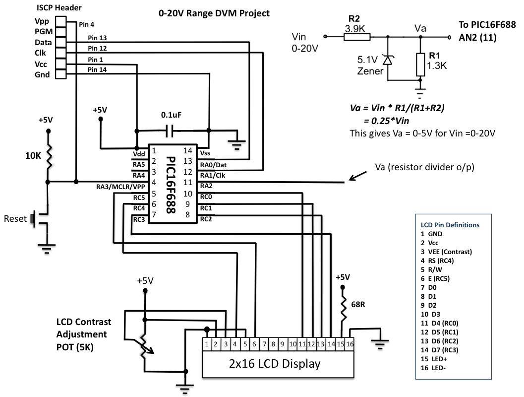
This is another version of an older digital voltmeter (DVM) project that was based on the PIC12F683 microcontroller. The previous version displayed the measured voltage on an LCD driven serially by the PIC12F683 using three I/O pins. The new...
The input mentions the 89S51/52 microcontrollers, but the accompanying image shows the 89C51. Clarification is needed regarding which microcontroller should be used with the provided .hex file without requiring changes to the file. The 89S51 and 89S52 are part of...
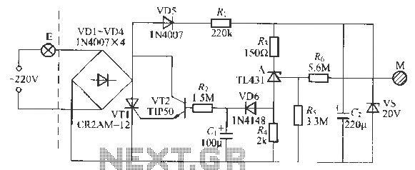
This circuit is a touch-sensitive lamp delay switch characterized by minimal static power consumption. It utilizes an external switch terminal, which can directly replace a standard switch. The circuit features a novel precision voltage regulator integrated circuit, such as...
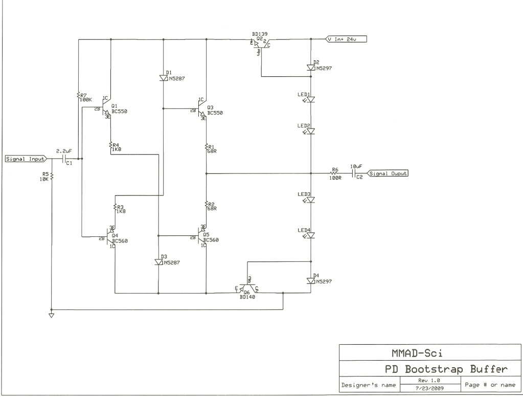
Various circuit variations have been explored, including a standalone preamp, headphone amplifier, replacements for the 321/729 circuits, and a potential active crossover, depending on demand. There has been significant interest in these designs, and the bootstrap buffer preamp is...