
PIC 18 Explorer Board LCD Example Code With SPI Library

The PIC 18 Explorer board is a versatile development platform that allows for the integration of various peripherals, including LCD displays. The SPI (Serial Peripheral Interface) library is a crucial component for facilitating communication between the microcontroller and the LCD. By employing this library, users can efficiently send data to the LCD, enabling the display of characters and graphics with minimal complexity.
To begin, the SPI library must be included in the project. This library provides functions that simplify the process of initializing the SPI interface, sending data, and managing the timing of data transmissions. The LCD display typically requires initialization commands to set its operating mode, such as character mode or graphic mode, and to configure its display parameters.
The connection between the PIC microcontroller and the LCD involves several pins: the Serial Data Input (SDI), Serial Clock (SCK), Chip Select (CS), and Data/Command (DC) lines. The SPI library manages these connections, allowing the microcontroller to send commands and data to the LCD in a synchronized manner. Proper timing is essential for ensuring that the LCD interprets the received data correctly.
In addition to controlling the LCD, the exploration of I/O expanders is pertinent. I/O expanders are integrated circuits that allow for the expansion of the number of input/output pins available on a microcontroller. This is particularly useful when additional peripherals, such as buttons or sensors, need to be interfaced with the PIC 18 Explorer board. The communication with I/O expanders can also be facilitated through protocols like I2C or SPI, depending on the specific expander used.
In summary, utilizing the SPI library with the PIC 18 Explorer board enables effective control of an LCD display, while understanding I/O expanders enhances the board's capability to manage multiple peripherals. This combination provides a robust foundation for developing complex electronic projects that require user interaction through visual displays and additional input/output functionalities.Learn to use the LCD display on your pic 18 explorer board with the spi library. The spi library will be used to easily display characters on the LCD. You will also learn how io expanders work. 🔗 External reference
Related Circuits
There have been numerous inquiries regarding this project, primarily due to issues with the source code provided at the end of the author's notes. This problem has been widely reported online, and similar compilation errors have been encountered. It...
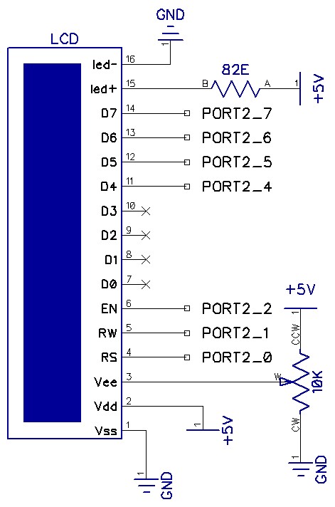
The circuit utilizes a total of seven pins from the microcontroller's GPIO. Consequently, the LCD module requires only one port out of four available. The EN line, known as "Enable," is a control line that indicates to the LCD...
Warning: Missing argument 2 for wpdb::prepare(), called in /home3/nithish/public_html/btechzone.com/wp-content/plugins/sharebar/sharebar.php on line 112 and defined in /home3/nithish/public_html/btechzone.com/wp-includes/wp-db.php on line 992 Warning: Missing argument 2 for wpdb::prepare(), called in /home3/nithish/public_html/btechzone.com/wp-content/plugins/sharebar/sharebar.php on line 124 and defined in /home3/nithish/public_html/btechzone.com/wp-includes/wp-db.php on line 992 This...
I found some similar circuits but aren't good enough for me. Some circuits measure the water's resistance to determine the level. That is dangerous for drinking water (contamination) or explosive liquids because electricity is in contact with water. The...
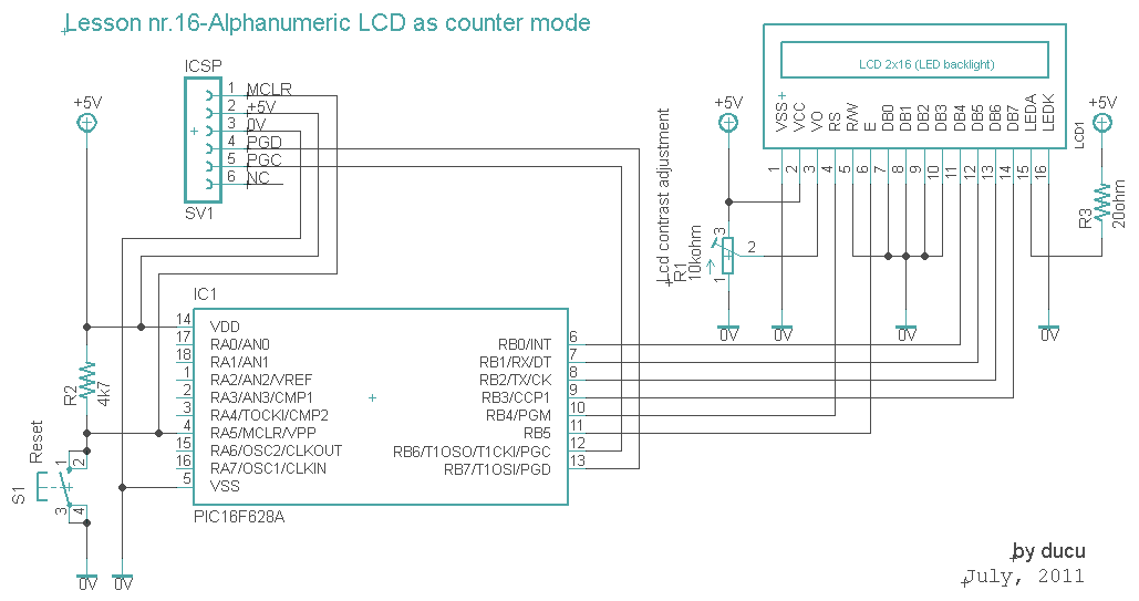
The communication technique with the LCD is similar to the previous lesson. In this experiment, a counter that counts from 0000 to 9999 has been added. The counter increments with a 1-second delay. The communication with the LCD will...
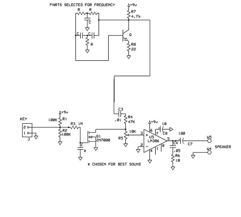
A schematic for a code practice oscillator is needed, which can be connected to a keyer. The desired setup involves using a Picokeyer, allowing the oscillator to be plugged into the key jack of the Picokeyer. The output should...