
PIC USB Interface

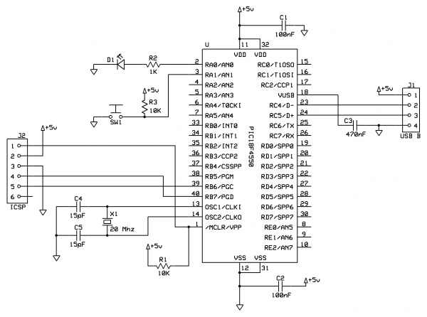
The described system operates as a simple serial communication interface between a microcontroller-based board and a personal computer. The program running on the microcontroller is designed to transmit a basic text message, "Hello world," to the PC, demonstrating fundamental serial communication principles.
The Virtual COM Port driver facilitates this communication by emulating a traditional serial port over USB. When the PCB is connected to the PC, the operating system recognizes the device and assigns it a COM port number, typically COM3: in this case, although this may differ based on the system's configuration and available ports.
To establish communication, the user must configure a terminal emulator, such as PuTTY or Hyperterminal, to match the serial settings of the microcontroller. The specified parameters—9600 BPS Baud rate, 8 data bits, no parity, and 1 stop bit—are standard for many serial communication applications, ensuring compatibility and reliable data transmission.
It is essential that the USB board is correctly configured to support these settings. This may involve setting the appropriate registers in the microcontroller firmware to enable the UART (Universal Asynchronous Receiver-Transmitter) module, which handles the serial communication. Proper initialization of the UART is critical for successful data transmission and reception.
In summary, this setup provides a straightforward method for sending data from a microcontroller to a PC, suitable for debugging and testing applications where simple text output is required. This basic example serves as a foundation for more complex serial communication tasks that can be developed as needed.The second program just sends "Hello world" to the PC. By default my board uses the Virtual COM Port (VCP) driver so you can view the output using Hyperterminal or similar program, I recommend PuTTY. The setup is quite simple, when I plug the PCB into my PC, it installs as COM3: (it will be different on your PC).
In the terminal program you select a Baud rate of 9600 BPS, 8 bits, no parity and 1 stop bit (standard settings) and connect using COM3: easy! This assumes your USB board is configured like this. 🔗 External reference
Related Circuits
New cellular phones have incorporated high-resolution cameras that require bright illumination of the surrounding area to achieve high-quality pictures. Traditional xenon-filled photo flashes cannot be used due to the limited space available in cellular phone cameras. Instead, design engineers...
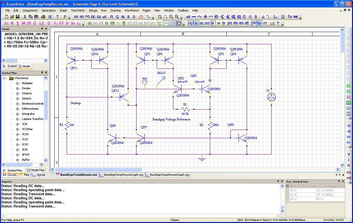
SuperSpice's philosophy is centered around the edit schematic, run simulation, view waveforms, probe signals, view waveforms, edit schematic cycle. All key issues have been automated. You can effortlessly modify the schematic, rerun and inspect new waveforms without having to...
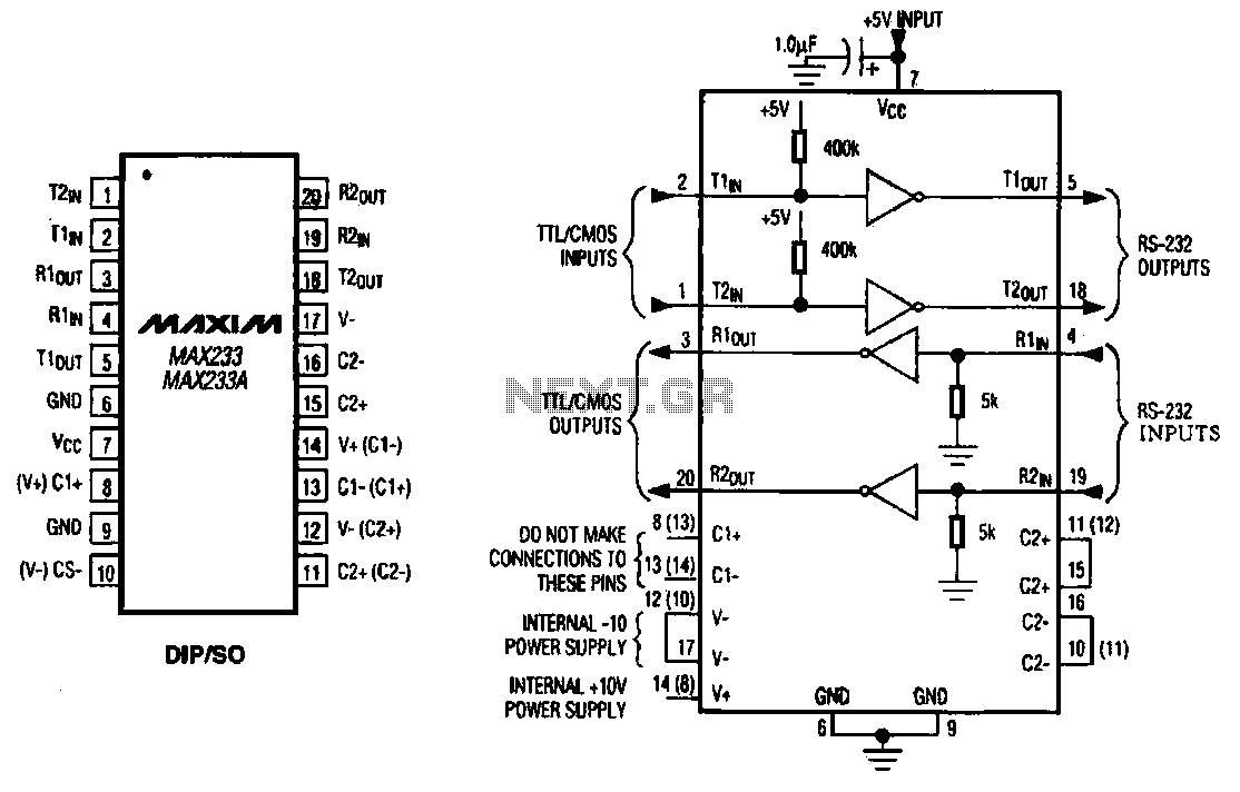
The MAX233 / 233A is a multi-channel data interface circuit featuring dual output and dual input driver circuits. It is designed for small digital products and multimedia equipment to facilitate data transmission. The MAX233 / 233A integrates multiple functions to...
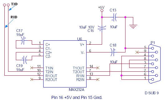
This document outlines the standard configuration for interfacing a microcontroller, such as the 8051, with a PC using RS232 through the MAX232A. The UART or serial port was absent in the 8049 and 8749 microcontrollers, which were predecessors to...

The camera operation failure on the Nokia 2630 has a similar solution to that of the Nokia 2600c, as both devices share the same circuit board. This issue is typically caused by hardware damage or a broken line on...
This tutorial provides guidance on creating a USB device, specifically a simple generic HID device using a breadboard. It covers the development of firmware for the PIC18F microcontroller and the creation of a Windows interface to control an LED...