
pic16f688 based digital voltmeter

The digital voltmeter (DVM) circuit operates by employing the PIC16F688 microcontroller, which enhances the design by allowing direct interfacing with an LCD in 4-bit mode. This reduces the number of required I/O connections and streamlines the overall design. The microcontroller's architecture supports an integrated analog-to-digital converter (ADC), enabling it to measure the input voltage accurately.
The circuit begins with the voltage source being fed into the ADC input pin of the PIC16F688. The ADC converts the analog voltage into a digital value, which is then processed by the microcontroller. The reference voltage for the ADC is set at +5V, which is derived from a regulated power supply. The LM7805 linear regulator is utilized to ensure that the voltage remains stable and within the required range for accurate readings.
In terms of the LCD interface, the PIC16F688 is configured to operate in 4-bit mode, which allows it to control the LCD using only four data lines and additional control lines for enabling and command functions. This configuration not only saves valuable I/O pins but also simplifies the wiring and layout of the circuit.
The software running on the PIC16F688 is designed to periodically sample the input voltage, convert it to a digital value, and display the result on the LCD. The display is updated at regular intervals to provide real-time voltage readings, and the code includes necessary functions for initializing the LCD, sending commands, and formatting the output for clear readability.
In summary, this updated DVM project showcases the advantages of using the PIC16F688 microcontroller for direct LCD interfacing and maintaining accuracy through a regulated power supply, while preserving the core principles established in the earlier PIC12F683 version.Actually this is the another version of my older DVM project that was based on PIC12F683. The older version displays the measured voltage on a LCD that is driven serially by PIC12F683 using 3 I/O pins. The new one uses PIC16F688 microcontroller that doesn`t require the serial driver as it has got enough pins to drive a LCD directly in 4-bit mode.
The theory and math is just the same. You can read my PIC12F683 version of this project here. Important: You need a regulated +5V supply for accuracy of the output. The ADC uses Vdd as the reference for conversion, and all computations are done with Vdd = 5V. You can get a regulated +5V using a LM7805 linear regulator IC. 🔗 External reference
Related Circuits

Vasilis Stergiopoulos has developed an RJ45 LAN cable tester. The circuit was initially designed to utilize a 555 timer and a 4017 decade counter IC, but Vasilis has released a schematic and assembly source code for implementing the Attiny2313...
The following circuit illustrates a curtain control circuit diagram. This circuit is based on the 555 integrated circuit (IC). Features include a switch for manual control, the IC, and additional components. The curtain control circuit utilizes the 555 timer IC...
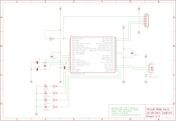
If you have experience with PIC18F microcontrollers and the USB Generic HID standard, you may have noticed the complexity involved in supporting USB on both the PIC18F and the Windows host side. Progressing beyond basic functionalities, such as reading...
Warning: Missing argument 2 for wpdb::prepare(), called in /home3/nithish/public_html/btechzone.com/wp-content/plugins/sharebar/sharebar.php on line 112 and defined in /home3/nithish/public_html/btechzone.com/wp-includes/wp-db.php on line 992 Warning: Missing argument 2 for wpdb::prepare(), called in /home3/nithish/public_html/btechzone.com/wp-content/plugins/sharebar/sharebar.php on line 124 and defined in /home3/nithish/public_html/btechzone.com/wp-includes/wp-db.php on line 992 This...

This FETVM replaces the function of the VTVM while eliminating the need for a traditional line cord. Additionally, it offers significantly improved drift rates compared to vacuum tube circuits, enabling a 0-volt full-scale range that is generally impractical with...
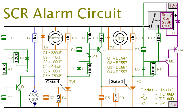
This is a simple SCR-based burglar alarm circuit. Its features include automatic exit and entry delays, along with a timed bell cut-off and reset. It is designed to be used with the usual types of normally-closed input devices such...