
Curtain ControlCircuit Based On The 555 IC

The curtain control circuit utilizes the 555 timer IC configured in monostable mode, allowing for precise control over the opening and closing of curtains. The circuit typically consists of a power supply, the 555 timer, a relay, and a switch for manual operation.
The power supply provides the necessary voltage to the circuit, usually in the range of 5V to 15V, depending on the specifications of the 555 IC and the relay used. The 555 timer is the central component, which generates a pulse when triggered by the manual switch.
The switch, when pressed, sends a trigger signal to the 555 timer, initiating the timing cycle. The duration of the pulse can be adjusted by changing the resistor and capacitor values connected to the timer. This timing determines how long the relay is activated, thus controlling the motor that opens or closes the curtains.
The relay acts as a switch that controls the motor's power supply. When the relay is energized by the output from the 555 timer, it closes the circuit to the motor, allowing it to operate and move the curtains. A diode may be included in parallel with the relay coil to prevent back EMF from damaging the 555 timer when the relay is deactivated.
This circuit can be enhanced with additional features such as a light sensor for automatic operation based on ambient light levels, or a remote control interface for added convenience. Overall, the curtain control circuit based on the 555 IC provides an effective solution for automated curtain management.The following circuit shows about Curtain Control Circuit Diagram. This circuit based on the 555 IC. Features: Switch for manual control, IC and a .. 🔗 External reference
Related Circuits
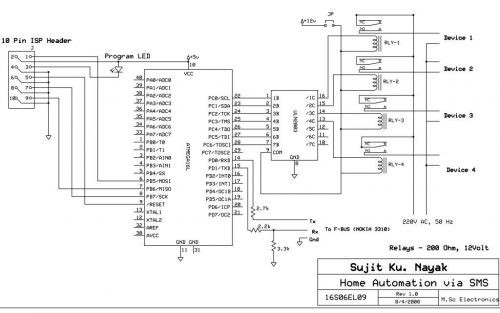
The project involves SMS control for older Nokia phones using the FBUS protocol, which is a complex communication method requiring detailed understanding and coding. The author has successfully implemented this project using an 89S52 microcontroller with only 256 bytes...
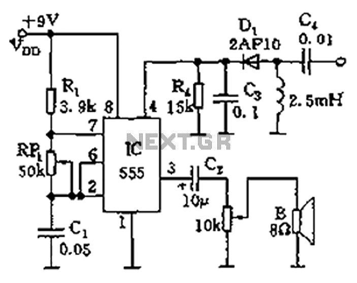
The circuit features a 555 timer integrated circuit along with components R1, RP1, C1, and others, which together form an audio oscillator. The frequency of the oscillator is determined by the formula f = 1.44 / ((R1 + 2...
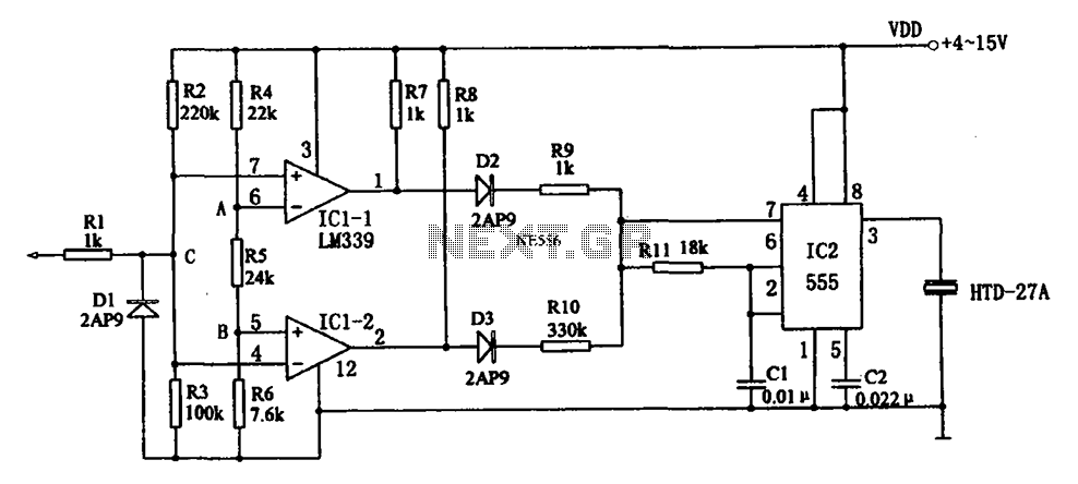
The acoustic logic level probe circuit consists of a voltage comparator, multivibrator, piezoelectric ceramics (HTD), and other components. The configuration of the audio circuit determines the frequency of the sound level to assess the logic levels of TTL or...
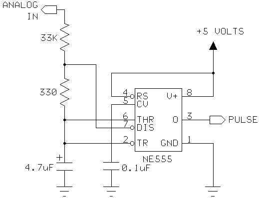
I had a Basic Stamp project that needed to measure a nominal 12 volt battery, and I wanted a simple solution. This is the simplest I could come up with. The 555 timer will put out positive pulses. The...
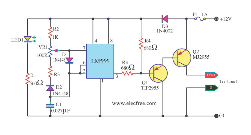
This circuit is a DC dimmer circuit that utilizes the LM555 integrated circuit configured as an astable multivibrator. It is capable of adjusting the duty cycle by fine-tuning variable resistors VR1 and VR2. The DC dimmer circuit employs the LM555...

A voltage-controlled oscillator using the NE555. This circuit is commonly referred to as a voltage-to-frequency converter because the output frequency is altered by varying the input voltage. As previously noted, pin 5 serves as the voltage control terminal, which...