
pic16f84

The PIC16F84 is an 8-bit microcontroller from Microchip Technology, widely utilized in various embedded applications due to its versatility and ease of use. It features a 14-bit instruction set architecture and is equipped with 1 KB of program memory and 64 bytes of RAM. The microcontroller operates at a maximum clock speed of 20 MHz, making it suitable for a range of timing-critical applications.
The ICSP (In-Circuit Serial Programming) interface allows for easy programming of the PIC16F84 while it is installed in the circuit. This feature is particularly advantageous for development and debugging, as it eliminates the need to remove the microcontroller from the circuit board for reprogramming.
The typical connection setup for the ICSP programmer involves the following pins: Vpp (Programming Voltage), Vdd (Power Supply), Vss (Ground), and the data lines for programming, which are usually MCLR (Master Clear), PGD (Program Data), and PGC (Program Clock). The MCLR pin is used to reset the microcontroller, while PGD and PGC facilitate data transfer during the programming process.
In a practical circuit example, the PIC16F84 can be connected to various peripheral devices such as LEDs, switches, and sensors. A basic circuit might include a power supply connected to the Vdd and Vss pins, with an LED connected to one of the I/O pins. The ICSP programmer would connect to the appropriate programming pins to enable firmware updates and debugging.
The schematic representation of the circuit will typically include the microcontroller, the ICSP connections, and any additional components required for the specific application. Proper layout and routing of the connections are essential to ensure reliable operation and to minimize interference, especially in high-frequency applications.A PIC16F84 introduction with ICSP programmer connection and circuit example.. 🔗 External reference
Related Circuits
To get enough outputs from the PIC chip, a pair of 74HC164 shift registers was used. These need only two lines from the PIC (data & shift) to produce the twelve signal pulses for the servos. A single bit...
This project is about an IR-detector (Infra Red) combined with a 100mW 50MHz transmitter. The detector is sensitive to changes in IR-spectrum and is commonly used in burglar alarms. When the detector senses a person/animal/ghost/angry clown, it will transmit...

Aircraft communication is still AM modulated and the frequency is about 110-125 MHz. What differs this construction from my two previous is that I have implemented many blocks into one circuit and therefore I will have superior performance with...
The previous version of this device used pulse width modulation (PWM) to control the power from the five solar panels to charge the battery bank. Under full sun conditions, the MOSFETs got a bit warm and the whole unit...

This is an early picture of my discolight effect. Because of the AGC circuit, there's no need for potentiometers for sensitivity adjustment. I replaced them with trimmers. Now the microphone is on the control electronics because there's no need...
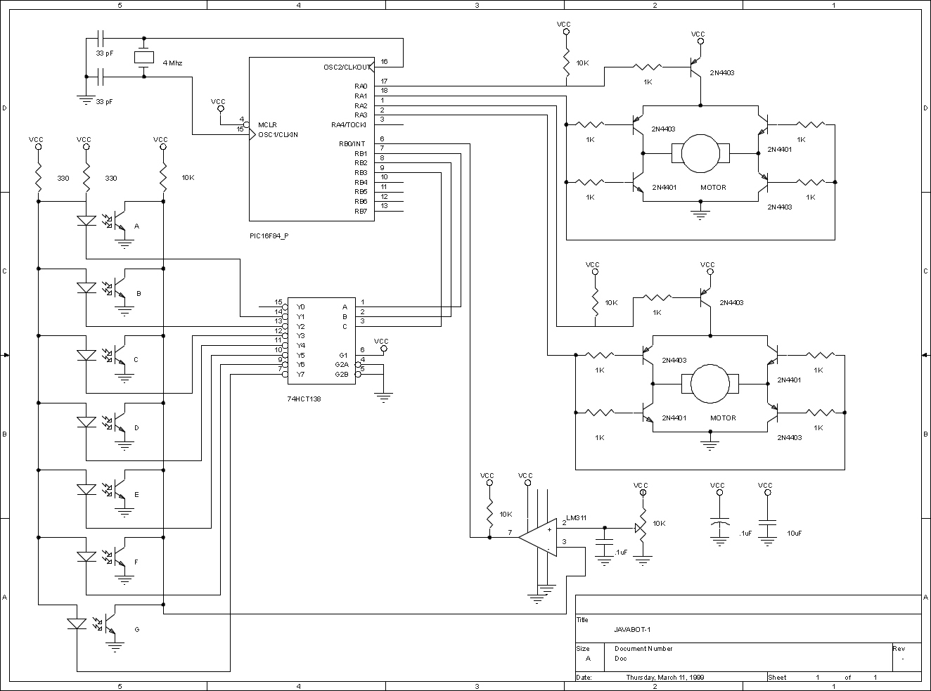
The JavaBot1 is a compact line-following robot engineered to trace a black line drawn on a dry erase board. It is specifically designed to navigate along very narrow curves. The JavaBot1 employs a differential drive mechanism, which allows it to...