
PICs in Space

The circuit design incorporates a Microchip PIC16F628A microcontroller, which serves as the core processing unit. The microcontroller executes all necessary functions for generating video and audio signals, ensuring a compact and efficient design. The power supply section consists of a battery connected to a power switch, with decoupling capacitors placed strategically to stabilize the power supply to the microcontroller. The design includes three user interface buttons connected with pull-up resistors, which can be used for game control, and a 9-pin D connector for an Atari-style joystick, providing flexibility in user input.
Programming capabilities are facilitated through an in-circuit programming connector, which allows for easy updates and modifications to the microcontroller's firmware. The microcontroller's clock is derived from a 20MHz crystal oscillator, ensuring precise timing for signal generation. The accompanying load capacitors are chosen to match the specifications of the crystal used, allowing for reliable operation.
Signal conditioning components, including resistors and capacitors, are utilized to ensure that the audio and video outputs meet the specifications required by the connected television. Basic anti-aliasing filters are implemented to enhance audio quality. The LED indicator provides a visual confirmation of circuit operation by lighting up when the RGB select pin is activated, a simple yet effective diagnostic feature.
The design emphasizes compatibility with modern televisions that support RGB input, which is crucial for achieving high-quality video output. The software controlling the microcontroller is complex and resource-intensive, utilizing nearly all available memory and storage capabilities of the device. This highlights the sophistication of the design, which leverages advanced programming techniques to deliver a functional gaming experience.
The prototype's physical construction demonstrates practical considerations in electronic design, such as mechanical stability and component placement, while also showcasing the use of readily available materials and enclosures. Overall, the circuit represents a comprehensive approach to creating a gaming console using a microcontroller, combining hardware and software elements to achieve the desired functionality.The circuit diagram is shown to the right. You can get a larger version or a PostScript version if you prefer. The design is based around a Microchip PIC16F628A microcontroller. At the time of writing, this device is available for less than one pound from (among others) Crownhill Associates. All the work, including colour video and synchronisatio n signal generation, is done in the microcontroller, and so there are no other active components. Purists who contend that the LED is an active component may replace it with a light bulb. We will describe the circuit from left to right. On the far left of the circuit diagram are the battery, power switch and decoupling capacitors. The smaller decoupling capacitor should be wired as close to the power pins of the microcontroller as possible. Three buttons with pull-up resistors provide the game controls. We have shown the buttons wired in parallel with a 9-pin D connector, into which you can plug an Atari-style digital joystick.
You can of course dispense with either the buttons or the connector if you wish. The connector to the above left of the microcontroller is for in-circuit programming of the device. You may need to change this part of the circuit to suit your programmer. Note that MCLR must be pulled high and RB4 pulled low for normal operation. The microcontroller derives its clock from a 20MHz crystal. The load capacitor values shown should be suitable for most readily-available crystals. A ceramic resonator could be used instead of the crystal, and should be accurate enough to allow most televisions to lock on to the resulting signal. On the right, a handful of resistors and capacitors match the audio (top right) and video (bottom right) signal levels to those required by the television.
Crude anti-alias filtering is provided for the audio. The LED lights when the microcontroller takes the RGB select pin on the SCART connector high: this occurs shortly after power-up, and so the LED provides some indication that the circuit is functioning correctly. Note that the SCART lead you use to connect the game to your television must be fully-wired: not all leads carry the RGB signals.
Your television must also be capable of accepting the RGB signals. Most modern televisions have at least one SCART input with this facility, though you may need to check the manual (or experiment) to determine which one it is. The software is by far the most complex part of the design, and it will not be described in detail here.
Large parts of it are automatically generated using specially-written tools. Almost all the resources of the PIC microcontroller are used: 99. 9% of the program memory (2046 out of 2048 locations), all but two of the data EEPROM locations, and almost all of the data RAM. You will need a programmer capable of writing to the program memory, data EEPROM and configuration bits of the device.
Here is the object code in Intel HEX format: many thanks to Adrian Higginson for preparing this file and testing it with MPLAB. The code is made available without warranty of any kind and is for hobby use only. Commercial use is not permitted. Here are a couple of pictures of the prototype, assembled using a DIL version of the microcontroller and mostly surface-mount resistors and capacitors.
Proper panel-mounted SCART connectors are hard, if not impossible, to obtain, and so the prototype employs a rather odd mounting arrangement to achieve mechanical strength. The corners have been cut away from the board so that it fits (just!) in a type H2855 ABS enclosure (available from Maplin Electronics) along with three AA cells.
The enclosure measures 83mm by 53mm by 31mm. Rickard GunG©e has described generating black-and-white video signals with a PIC microcontroller, making a Tetris game and a Pong game. He has also made similar games using a Scenix microcontroller and an external digital-to-analogue converter to produce an NTSC composit
🔗 External reference
Related Circuits
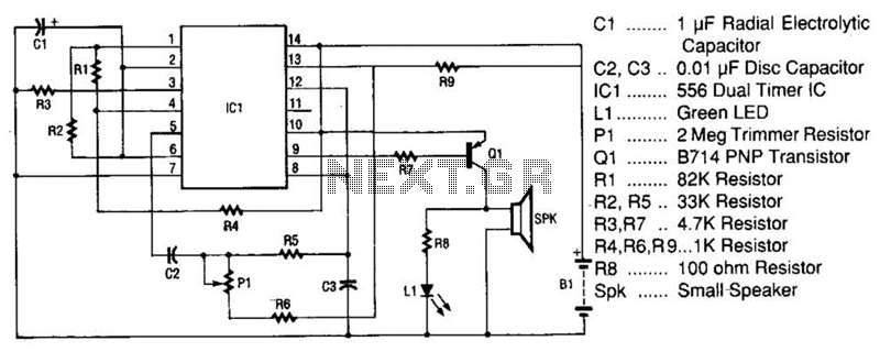
The space-age sound device utilizes a 556 dual timer integrated circuit (IC) to generate a phasor sound. This IC consists of two 555 timer circuits within a single 14-pin package, as depicted in the schematic. Each timer operates in...
The one-shot and decay functions could be added to create an ideal phasor gun sound. To design a circuit that generates a phasor gun sound using one-shot and decay functions, the following components and configuration can be utilized. The one-shot...
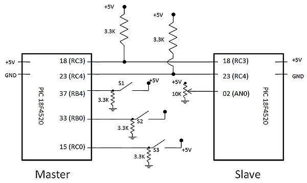
I2C, pronounced "I squared C," stands for Inter-Integrated Circuit. This protocol was developed by Philips Semiconductors around 1992 to facilitate easy communication between components on the same circuit board, achieving transfer rates of up to 400 kbit/sec. It utilizes...
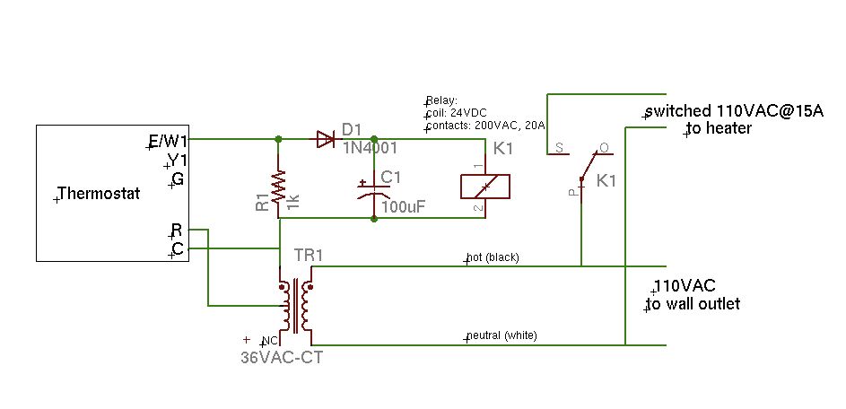
A basic schematic of the circuit is presented, marking the initial experience with Eagle software. It is important to note that only the W1 output of the thermostat is utilized, while C serves as the common connection. The schematic outlines...

This type of travel may be possible if two space points can be connected by a vortex channel in aether. The channel allows continuity of matter, energy, and life by establishing a connection between two distant points. The vortex...
On astable multivibrators, the duty cycle is typically fixed unless a potentiometer is incorporated. However, even with a diode in parallel with resistor R2, the duty cycle will only be less than 50%. To initiate a new thread, one...