Pioneer CLD-1090

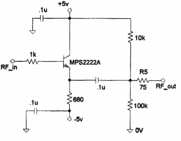
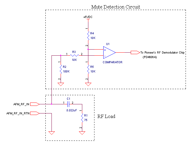
Instructions for adding an AC-3 RF output to older laser disc players are outlined. Kevin Nakano's webpage provided valuable guidance, specifically detailing modifications for the CLD-D702 model. The CLD-1090 is similar to the CLD-D702, though the board layout differs slightly. General instructions are provided to assist users with Pioneer CLD-XXXX models in modifying their devices. A common concern regarding modifications is the fabrication of the circuit board. A custom-etched board simplifies assembly and minimizes wire lengths, but a generic Radio Shack board can also be utilized. The circuit is straightforward and can be assembled in approximately 30 minutes. The board (part # 276-159) features several sets of five interconnected holes. The assembly process involves selecting a location for the transistor and soldering it in place, followed by connecting components according to the schematic. The circuit design utilizes a single transistor, four resistors, and three capacitors. An image of the opened laser disc player is referenced, indicating where the RF section is located. The original screw for the S-video jack is replaced with a bolt and nut to secure the new circuit. The basic circuit schematic is modeled after circuit #2 from Nakano's webpage, employing an MPS2222A transistor with a bandwidth of 300 MHz. This configuration operates as an emitter follower/common collector, ensuring high input impedance and low output impedance to prevent loading the RF section of the laser disc player. Most resistors can be sourced from Radio Shack, and a 75-ohm resistor can be created by connecting two 150-ohm resistors in parallel. A 68-ohm resistor is also available. The circuit omits the mute section, as initial tests showed no noise during player inactivity. However, sound from the laser disc may be audible during chapter transitions, but it does not exceed the volume of the movie. For those interested in adding the mute section, further resources are provided. Locating the RF tap is the most complex aspect, with markings on the board indicating "RF level," 2.3 MHz, and 2.8 MHz. The transistor required is located near Q351 and Q352, with the RF input connected to the emitter of Q352, which is a 2SC1740S. Differences in board layout may exist, as noted by variations in the coil position (LF353) on different models. The emitter leg of Q352 is identified as the left leg when facing the printed side. The configuration may vary among different CLD-XXXX players, as demonstrated by a friend's CLD-A100 model, which features distinct layout and part designations due to additional karaoke and game options.
The modification process for adding an AC-3 RF output to older laser disc players involves careful planning and execution. The first step includes identifying the correct model and obtaining the necessary components. The circuit board chosen for the modification should accommodate the components while ensuring minimal interference with existing circuitry.
The MPS2222A transistor serves as a critical component due to its suitable bandwidth and configuration. The emitter follower arrangement is particularly advantageous in this application, as it maintains the integrity of the RF signal without loading the previous stages of the circuit. This is essential for preserving audio quality and ensuring that the output remains faithful to the original source material.
When assembling the circuit, attention must be paid to the layout and connections to prevent shorts or signal degradation. The use of a breadboard for initial testing may facilitate troubleshooting before finalizing the circuit on the more permanent board.
Once the assembly is complete, thorough testing should be conducted to ensure that the RF output functions as intended. This includes checking for signal clarity and verifying that the modification does not introduce unwanted noise or distortion.
Documentation of the modification process, including photographs and notes on component placement, can be beneficial for future reference or for others attempting similar modifications. This ensures that the knowledge is shared within the community, allowing for further enhancements and refinements to the process.
Overall, the successful addition of an AC-3 RF output not only enhances the functionality of older laser disc players but also contributes to the preservation of vintage audio-visual technology.How to add an AC-3 RF output to older laser disc players. Finally I was ready to try it myself. Kevin Nakano`s web page (link below) was very helpful. His page describes how to do the modification to a CLD-D702. My CLD-1090 is very similar to the CLD-D702. The board layout is slightly different and by describing in general terms how to get the RF tap I hope others with Pioneer CLD-XXXX models can figure out how to modify their own machines. (The board) One of the things that scares people away from doing there own mods is the fabrication of the circuit board. A custom etched board makes things easy to put together and minimizes wire lengths but a generic Radio Shack board can be used.
The circuit is very simple and the Radio Shack board is small. The circuit board (part # 276-159) has several sets of 5 holes that are connected together. The best way to build the circuit is to choose a spot for the transistor and solder it in. Then using the schematic connect everything together as needed. My version of the circuit uses only 1 transistor, 4 resistors, and 3 capacitors. It can be assembled in 30 minutes. The picture to the right shows the opened laser disc player. Click on the picture to get the big version so you can see in general where the R. F section may be on your player. You can see where I mounted my board. I removed the screw holding the S-video jack and replaced it with a bolt and nut. The bolt holds the new circuit out of harms way. The circuit The basic circuit schematic is similar to circuit #2 from Nakano`s web page. I used a MPS2222A transistor from radio shack. It has a wide (300MHZ) band width suitable for this project. The circuit is a Emitter follower/Common collector. This configuration gives a fairly high input impedance and a low output impedance. This way you won`t load down the RF section of the LD player. Most of the resistors are available at radio shack. I made a 75 ohm resistor by putting two 150 ohm resistors in parallel. The 68 Ohm resistor radio shack sells should be fine. I used. 25 Watt resistors when possible to save space. You may notice that I left the mute part of the circuit off. When I was building the circuit I wanted to try the main part out before I continued. I noticed that with out the mute circuit I had no noise when the player was in stop, pause, or skipping between chapters. I did notice some sound from the L. D. does come through when there is no picture (mostly between chapters). However the sound is not any louder that the volume you are playing the movie at. It is sound from the movie and not noise. That does not bother me so I never added the mute part of the circuit. If you do decide you would like to add the mute section check the links below. (RF tap) Finding the place to get your RF is the most challenging part of the adventure. You will probably see marks on the board like "RF level", 2. 3MHZ, 2. 8MHZ. The transistor you need should be located close by. You should find Q351 and Q352 right next to each other. You need to connect to the emitter of Q352 to get your RF input to your board. Q352 should be a 2SC1740S. I noticed that the board on Kevin Nakano`s page differed here. He used the position of the coil (LF353) to describe what leg of the transistor should be used. In the CLD-1090 and maybe others the coil is in a different location relative to Q352. Look at the transistor so you are facing the printed side that shows the 2SC1740S part #. The emitter should be the leg on the left. I looked up the transistor in the the NTE cross reference book to see what leg was the emitter. I also confirmed the books information with a meter. Not all CLD-XXXX players will have Q351 and Q352. My friends CLD-A100 was very different. The layout of the boards and part designations were not similar to mine because his player has Karoke and game options.
There was a lot of surface moun 🔗 External reference

