
Pioneer CLD-1950

This modification is to be performed at your own risk, and there is no guarantee that it will work for you. Improper installation of this design may result in damage to you and/or your laserdisc player. This website does not take responsibility for any modifications attempted. The following is a step-by-step description of how to modify a Pioneer CLD-1950 laserdisc player to output the Dolby Digital (AC-3) RF signal required for Dolby Digital demodulators/decoders. The intention is to assist those interested in modifying their own player, thereby avoiding the cost of upgrading to a new machine or paying a significant amount for services that provide the Dolby Digital modification. The custom board detailed here contains the necessary AC-3 circuitry. Once installed, the card enables older, non-AC-3 laserdisc players to output the highly discussed AC-3 RF signal. The circuit used was sourced from Kevin's webpage. Instead of the 2SA1037K and the UN2112, the BC808 was utilized, which is available in Europe. This required adding a pull-up resistor from the base of Q2 to +5VDC, as well as a series resistor from the same base to the mute input of the board. A value of 22k was used for both resistors, although this value is not critical. This version of the board incorporates metal film surface mount resistors, surface mount ceramic capacitors, and transistors to minimize noise levels in the signal. Players that have factory-installed AC-3 circuitry typically also utilize surface mount components. The circuit board was constructed using a printout from a custom circuit board program. The new circuit card requires two voltage levels (+5VDC, -5VDC) and a ground connection. Power is drawn from these three lines as indicated in the accompanying photo; red indicates +5VDC, while yellow indicates -5VDC. Ground is sourced from the signal input, and the power lines are routed to the newly installed AC-3 card. The AC-3 RF output is sent to the back panel through an RCA connector. Care should be taken to prevent metal shavings from falling into the unit during drilling. Tape and paper can be used to cover the inside during this process. After drilling, the RCA connector is installed with nylon washers to insulate it from the chassis. It should be noted that the outer portion of the connector will eventually be AC coupled to the chassis via a 0.1uF capacitor. A shielded 75 Ohm video cable is recommended. The current AC-3 RF outputs on production laserdisc players contain both left and right AFM signals. The demodulator/decoder unit must first band-pass filter and then demodulate the right channel (2.8 MHz carrier) to recover the AC-3 bitstream. If an additional RF bitstream is added to the left channel (2.3 MHz), no further modifications will be required in the laserdisc player, as it already outputs both RF channels. The left side of the photo shows the crucial connection point for the AFM RF signal feeding the AC-3 card. The purple wire connects to the AFM signal, while the black wire serves as ground. A connector was installed, and the wires were soldered to this connector. The mute signal is sourced from a wire near the A/D converter (the IC marked "Pulseflow") on the main board, indicated by the green wire in the photo. This active high MUTE signal is necessary to correctly set the DC level of the AC-3 RF signal during mute mode. Upon completion of the project, the voltage levels should be checked using an oscilloscope or voltmeter to ensure the modification is functioning correctly. The AC portion of the waveform should be approximately 0.6 Vp-p with no load, while the DC levels should be around 4.6 V. If the signal is muted, the DC level will drop to zero, but the AC portion of the waveform should remain unchanged, even during muting. AC-3 demodulators/decoders utilize a DC level detection circuit to determine whether the audio should be muted.
The modification of a Pioneer CLD-1950 laserdisc player to enable Dolby Digital (AC-3) RF output involves several critical steps and components. The core of the modification is the custom circuit board that integrates essential AC-3 circuitry. This board's design allows for the output of the AC-3 RF signal, which is crucial for compatibility with Dolby Digital demodulators and decoders.
The choice of components is vital, particularly the substitution of the 2SA1037K and UN2112 with the BC808 transistor. This substitution necessitates additional circuitry adjustments, such as the incorporation of pull-up and series resistors to ensure proper operation of the mute function and signal integrity. The use of metal film surface mount resistors and ceramic capacitors is recommended to reduce noise, which is particularly important in audio applications where signal clarity is paramount.
Powering the circuit board requires a dual voltage supply of +5VDC and -5VDC, along with a common ground. Careful routing of these power lines is essential to maintain signal integrity and prevent interference. The RCA connector serves as the output interface, and proper installation is critical to avoid short circuits or grounding issues.
The integration of the AC-3 RF output into the existing laserdisc player architecture allows for enhanced audio capabilities without the need for a complete system upgrade. The careful selection of materials and adherence to electrical specifications ensures that the modification is both effective and reliable. Post-installation testing using an oscilloscope or voltmeter is crucial to verify that the modification meets expected performance metrics, such as waveform characteristics and DC levels, ensuring that the audio output functions as intended.This modification is to be done AT YOUR OWN RISK and there is no guarantee that the modification will work for you. Failure to properly install this design correctly may result in damage to you and/or your laserdisc player.
This web site takes no responsibility for any modification you may attempt. The following shows a step-by step description on how I modified my Pioneer CLD-1950 laserdisc player to output the Dolby* Digital (AC-3) RF signal needed to drive Dolby Digital demodulators/decoders. My intention is to help those interested in modifying their own player; thereby avoiding the cost of upgrading to a new machine or paying a large sum of money to services that provide the Dolby Digital modification.
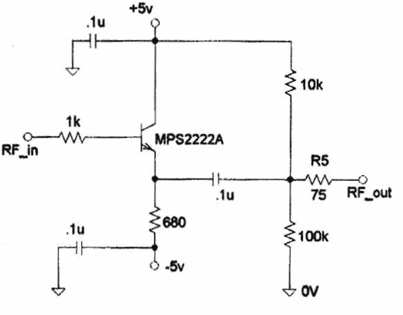
The custom board shown here holds the required AC-3 circuitry. Once installed, the card enables older, non-AC-3 laserdisc players the ability to output the much talked about AC-3 RF signal. The circuit I used came from Kevin`s web page. Instead of the 2SA1037K and the UN2112 I used the BC808, which is available in Europe. This made it necessary to add a pullup from the base of Q2 to +5VDC, and a series resistor from the same base to the mute input of the board.
I used 22k for each resistor, the value is not critical though. This version of the board uses metal film surface mount resistors as well as surface mount ceramic capacitors and transistors to minimize the level of noise in the signal. Players which have the AC-3 circuitry from the factory, typically use surface mount components as well.
The card was constructed using a printout from the circuit board program I have written myself. The new circuit card needs two voltage forms (+5VDC, -5VDC) and a ground. Power is tapped from these three lines as indicated in the photo. Red carries the +5VDC; Yellow carries the -5VDC. Ground will be fetched from the signal input. The power lines are routed to the newly installed AC-3 card. The AC-3 RF output is sent to the back panel through an RCA connector. Make sure when you drill the hole you don`t let any metal pieces fall into the unit. I used some tape and paper to cover the inside during drilling. Once the hole is drilled out, the RCA connector is installed with nylon washers to insulate the connector from the chassis. Note: The outer portion of the connector will eventually be AC coupled to the chassis through a 0. 1uF capacitor. Be sure to use a shielded 75 Ohm video cable! NOTE: The current AC-3 RF outputs on production LD players contain both the left and right AFM signal.
The demodulator/decoder unit must first band-pass filter and then demodulate the right channel (2. 8 MHz carrier) to recover the AC-3 bitstream. If an additional RF bitstream is ever added to the left channel (2. 3 MHz), no additional modification will be required in the LD player since it already outputs both RF channels. The left of the picture shows the most important bit: this is where the AFM RF signal that feeds the AC3-card comes from.
The purple wire is connected to the AFM signal, and the black wire is ground. I installed a connector and soldered the wires to this connector. The mute signal is picked up from a wire near the A/D converter (the IC marked "Pulseflow") on the main board. It is the green wire shown on the picture. This active high MUTE signal is needed to properly set the DC level of the AC-3 RF signal during the mute mode.
Now that your project is complete, you should check the voltage levels using a scope and/or a voltmeter to insure your modification is working correctly. The AC portion of the waveform should be approximately 0. 6 Vp-p with no load. The DC levels should be approximately 4. 6 V. If the signal is muted, the DC level will go to zero. The AC portion of the waveform should remain the same, even during muting. AC-3 demodulators/decoders use a DC level detection circuit to determine if the audio should be muted or not.
The muting threshold voltage received b 🔗 External reference
The modification of a Pioneer CLD-1950 laserdisc player to enable Dolby Digital (AC-3) RF output involves several critical steps and components. The core of the modification is the custom circuit board that integrates essential AC-3 circuitry. This board's design allows for the output of the AC-3 RF signal, which is crucial for compatibility with Dolby Digital demodulators and decoders.
The choice of components is vital, particularly the substitution of the 2SA1037K and UN2112 with the BC808 transistor. This substitution necessitates additional circuitry adjustments, such as the incorporation of pull-up and series resistors to ensure proper operation of the mute function and signal integrity. The use of metal film surface mount resistors and ceramic capacitors is recommended to reduce noise, which is particularly important in audio applications where signal clarity is paramount.
Powering the circuit board requires a dual voltage supply of +5VDC and -5VDC, along with a common ground. Careful routing of these power lines is essential to maintain signal integrity and prevent interference. The RCA connector serves as the output interface, and proper installation is critical to avoid short circuits or grounding issues.
The integration of the AC-3 RF output into the existing laserdisc player architecture allows for enhanced audio capabilities without the need for a complete system upgrade. The careful selection of materials and adherence to electrical specifications ensures that the modification is both effective and reliable. Post-installation testing using an oscilloscope or voltmeter is crucial to verify that the modification meets expected performance metrics, such as waveform characteristics and DC levels, ensuring that the audio output functions as intended.This modification is to be done AT YOUR OWN RISK and there is no guarantee that the modification will work for you. Failure to properly install this design correctly may result in damage to you and/or your laserdisc player.
This web site takes no responsibility for any modification you may attempt. The following shows a step-by step description on how I modified my Pioneer CLD-1950 laserdisc player to output the Dolby* Digital (AC-3) RF signal needed to drive Dolby Digital demodulators/decoders. My intention is to help those interested in modifying their own player; thereby avoiding the cost of upgrading to a new machine or paying a large sum of money to services that provide the Dolby Digital modification.
The custom board shown here holds the required AC-3 circuitry. Once installed, the card enables older, non-AC-3 laserdisc players the ability to output the much talked about AC-3 RF signal. The circuit I used came from Kevin`s web page. Instead of the 2SA1037K and the UN2112 I used the BC808, which is available in Europe. This made it necessary to add a pullup from the base of Q2 to +5VDC, and a series resistor from the same base to the mute input of the board.
I used 22k for each resistor, the value is not critical though. This version of the board uses metal film surface mount resistors as well as surface mount ceramic capacitors and transistors to minimize the level of noise in the signal. Players which have the AC-3 circuitry from the factory, typically use surface mount components as well.
The card was constructed using a printout from the circuit board program I have written myself. The new circuit card needs two voltage forms (+5VDC, -5VDC) and a ground. Power is tapped from these three lines as indicated in the photo. Red carries the +5VDC; Yellow carries the -5VDC. Ground will be fetched from the signal input. The power lines are routed to the newly installed AC-3 card. The AC-3 RF output is sent to the back panel through an RCA connector. Make sure when you drill the hole you don`t let any metal pieces fall into the unit. I used some tape and paper to cover the inside during drilling. Once the hole is drilled out, the RCA connector is installed with nylon washers to insulate the connector from the chassis. Note: The outer portion of the connector will eventually be AC coupled to the chassis through a 0. 1uF capacitor. Be sure to use a shielded 75 Ohm video cable! NOTE: The current AC-3 RF outputs on production LD players contain both the left and right AFM signal.
The demodulator/decoder unit must first band-pass filter and then demodulate the right channel (2. 8 MHz carrier) to recover the AC-3 bitstream. If an additional RF bitstream is ever added to the left channel (2. 3 MHz), no additional modification will be required in the LD player since it already outputs both RF channels. The left of the picture shows the most important bit: this is where the AFM RF signal that feeds the AC3-card comes from.
The purple wire is connected to the AFM signal, and the black wire is ground. I installed a connector and soldered the wires to this connector. The mute signal is picked up from a wire near the A/D converter (the IC marked "Pulseflow") on the main board. It is the green wire shown on the picture. This active high MUTE signal is needed to properly set the DC level of the AC-3 RF signal during the mute mode.
Now that your project is complete, you should check the voltage levels using a scope and/or a voltmeter to insure your modification is working correctly. The AC portion of the waveform should be approximately 0. 6 Vp-p with no load. The DC levels should be approximately 4. 6 V. If the signal is muted, the DC level will go to zero. The AC portion of the waveform should remain the same, even during muting. AC-3 demodulators/decoders use a DC level detection circuit to determine if the audio should be muted or not.
The muting threshold voltage received b 🔗 External reference
Related Circuits
Instructions for adding an AC-3 RF output to older laser disc players are outlined. Kevin Nakano's webpage provided valuable guidance, specifically detailing modifications for the CLD-D702 model. The CLD-1090 is similar to the CLD-D702, though the board layout differs...
After restoring a Fisher 400, the search for another tube amplifier began, motivated by a desire to apply newly acquired skills. Importing equipment from the USA to the European Union proved costly, with shipping fees around $200 to $250,...