
PIR Motion Sensor

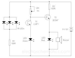
The PIR (Passive Infrared) motion sensor circuit is designed to detect motion based on changes in infrared radiation levels in the environment. This circuit typically consists of a PIR sensor module, which includes pyroelectric sensors that detect body heat. When a warm body, such as a human or animal, passes within the sensor's range, it triggers a change in the output voltage of the sensor.
The circuit is composed of the following key components:
1. **PIR Sensor**: The core component responsible for detecting motion. It contains two pyroelectric elements that generate a voltage when exposed to infrared radiation. The sensor has a specific detection angle and range, usually around 120 degrees and up to 10 meters, respectively.
2. **Operational Amplifier (Op-Amp)**: An op-amp is used to amplify the weak signal generated by the PIR sensor. This amplification is crucial for ensuring that the output signal is strong enough to trigger subsequent components in the circuit.
3. **Resistors and Capacitors**: These passive components are used to set the gain of the op-amp and to filter the output signal. They help stabilize the circuit and prevent noise from affecting the performance.
4. **Output Stage**: The output from the op-amp can be connected to various devices, such as a relay for activating alarms, lights, or other electronic devices. This output stage may include additional components like transistors to handle higher current loads.
5. **Power Supply**: The circuit requires a stable power supply, typically 5V to 12V, depending on the specifications of the PIR sensor and other components used.
The design emphasizes simplicity and high efficiency, making it suitable for various applications, including security systems, automatic lighting, and energy-saving solutions. The integration of operational amplifiers enhances the circuit's capability to accurately detect motion and minimize false alarms, thereby improving overall performance.The following circuit shows about PIR Motion Sensor Circuit Diagram. Features: simple and high efficiency, operational amplifiers a sound .. 🔗 External reference
Related Circuits

This line-following robot sensor, also known as a surface scanner for robots, is a compact, stamp-sized infrared proximity detector designed for short-range detection (5-10 mm). It is built around a standard reflective opto-sensor, the CNY70 (IC1). In various applications,...
The circuit utilizes the widely used Sharp IR module (the Vishay module can also be employed). The pin numbers indicated in the circuit are applicable to both the Sharp and Vishay modules. For other modules, it is advisable to...

In this circuit, the LM335 is utilized as a temperature sensor, an integrated circuit that converts ambient temperature into an equivalent output voltage. The LM335 is a precision temperature sensor that provides a linear output voltage proportional to the absolute...

The simple pressure sensor alarm is constructed using a few inexpensive and readily available components. The operation of this circuit is straightforward and self-explanatory. When powered by a 9V compact battery, the active piezo sounder at the output of...

The following circuit illustrates a simple battery charger equipped with a temperature sensor. This circuit is based on the LM350 integrated circuit. Features include negative... The circuit utilizes the LM350 voltage regulator IC, which is known for its ability to...
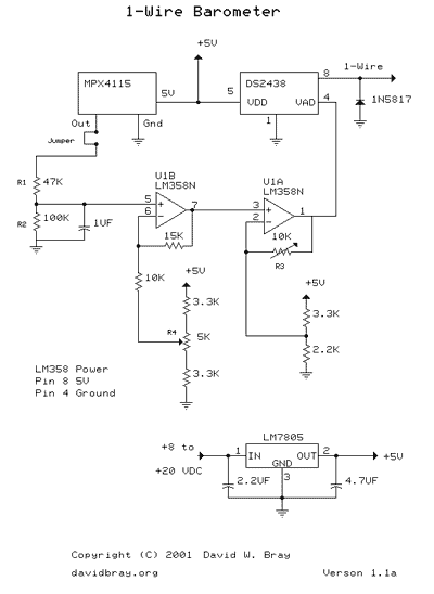
This design uses a Motorola MPX4115 Silicon Pressure Sensor, a Dallas Semiconductor DS2438 Smart Battery Monitor (to perform 1-Wire analog to digital conversion), an operational amplifier, a voltage regulator, a diode, and several resistors and capacitors. The circuit requires...