
Simple Battery Charger With The Temperature Sensor

The circuit utilizes the LM350 voltage regulator IC, which is known for its ability to provide adjustable output voltage and current regulation. The configuration includes a temperature sensor, which serves to monitor the battery temperature during the charging process. This is crucial for safety, as overheating can lead to battery damage or failure.
The primary components of the circuit include the LM350, resistors for setting the output voltage, capacitors for stability, and a temperature sensor such as the LM35, which outputs an analog voltage proportional to the temperature. The LM350 is connected in a typical linear voltage regulator configuration, where the input voltage is applied to the input pin, and the output voltage is taken from the output pin after passing through the resistive divider network.
The temperature sensor is connected to a microcontroller or comparator circuit, which can shut down the charging process if the battery temperature exceeds a predetermined threshold. This feature enhances the safety of the charging system by preventing thermal runaway conditions.
Additionally, the circuit may include LED indicators to show the charging status, as well as protection diodes to prevent reverse polarity connections. Proper heat sinking for the LM350 is also recommended, as the device may dissipate significant power depending on the input voltage and load current.
Overall, this simple battery charger circuit with a temperature sensor is an effective solution for safely charging batteries while monitoring their temperature to prevent damage.The following circuit shows about Simple Battery Charger With The Temperature Sensor. This circuit based on the LM350 IC. Features: negative .. 🔗 External reference
Related Circuits
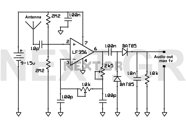
This AM receiver is working perfectly without the need of coils or even a variable capacitor. The LF356 is the basic component. P1 and P2 are the frequency selectors. Use a small telescopic antenna. The stations selectivity is not...
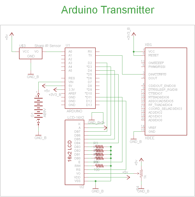
The schematic for the transmitter in this project consists of four main components: the Arduino UNO, the Sharp IR distance sensor, the XBee wireless modules, and a 16x2 LCD. The connections between these components are illustrated in the schematic....
This circuit is designed to eliminate internal shorts in nickel-cadmium batteries. To operate, connect the nickel-cadmium battery to the output and press the pushbutton for three seconds. The circuit functions by utilizing a controlled discharge process to clear internal shorts...
The intention is to utilize the sensor as a force sensor. It has been observed that the voltage output increases with the amount of pressure applied, although this output is only sustained for a brief period. This behavior is...
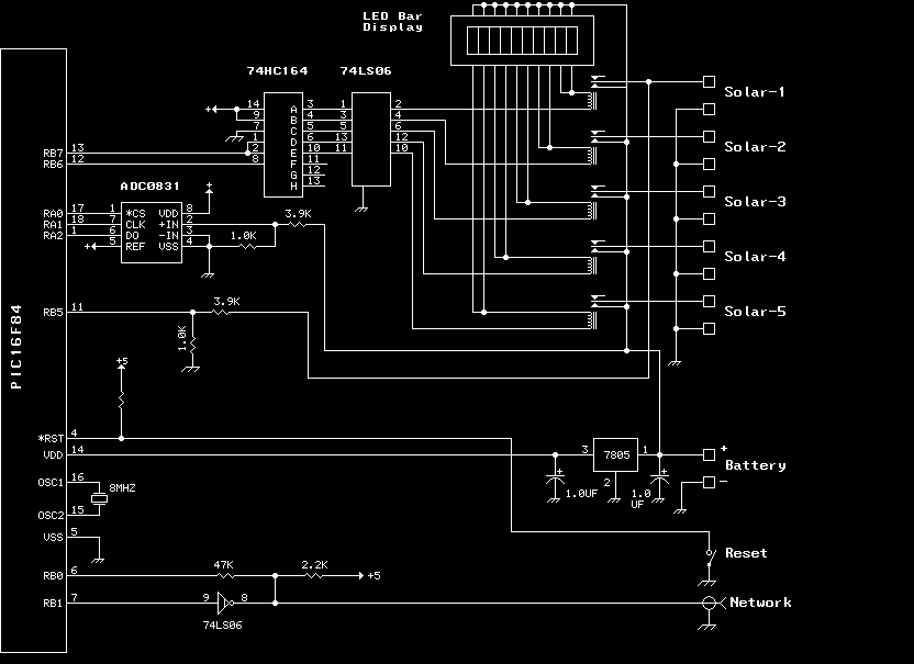
The previous version of this device used pulse width modulation (PWM) to control the power from the five solar panels to charge the battery bank. Under full sun conditions, the MOSFETs got a bit warm and the whole unit...
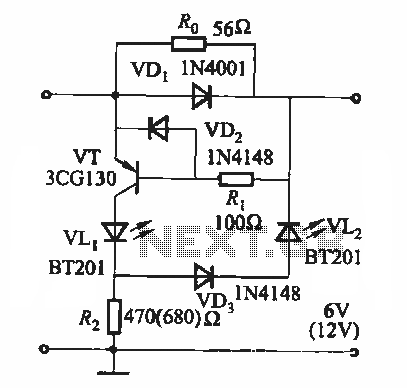
During the charging process, the green light-emitting diode (LED) VLi indicates that the battery is sufficiently charged, while the red light-emitting diode (LED) VLz illuminates when the battery is low. The circuit involves two light-emitting diodes (LEDs) serving as indicators...