
place the potentiometer
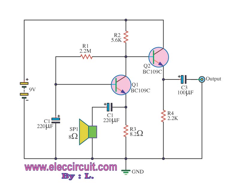
The preamplifier circuit is designed to increase the amplitude of weak audio signals from a small speaker, making it suitable for further processing or amplification. The circuit typically includes several key components: resistors, capacitors, transistors or operational amplifiers, and power supply connections.
The input stage of the preamplifier receives the audio signal from the small speaker. This signal is often weak and requires initial amplification. A common configuration involves using a transistor or an operational amplifier (op-amp) in a non-inverting amplifier setup. The gain of the amplifier can be set using feedback resistors, allowing for customization based on the specific requirements of the audio source.
Capacitors are used in the circuit to block any DC offset from the audio signal, ensuring that only the AC component (the actual audio signal) is amplified. Additionally, coupling capacitors may be employed at the input and output stages to prevent unwanted frequency responses and to stabilize the circuit.
Power supply considerations are crucial for the preamp design. Depending on the chosen components, the circuit may require a dual power supply (positive and negative voltages) or a single supply with appropriate biasing to ensure linear operation of the amplifier.
Overall, the design of the preamplifier must take into account factors such as input impedance, output impedance, and the desired frequency response to ensure compatibility with subsequent audio processing stages. Proper layout and grounding techniques are also essential to minimize noise and interference, which can adversely affect audio quality.This might seem like a dumb question, but I`m a total newb in electronics. I built this preamp to amplify the signal from a small speaker that i use.. 🔗 External reference
Related Circuits
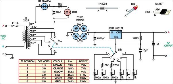
The battery-operated toy has malfunctioned, necessitating repair. Upon disassembly, the battery compartment may be disconnected from the circuitry, or the batteries might be depleted. A solution is to implement a switchable power supply designed to replace one to six...
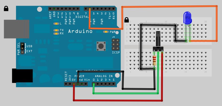
The analog to digital sketches have been extensively covered using various components. To progress to more complex circuits and concepts, it is essential to understand these simpler ones. This tutorial will not delve as deeply as others due to...
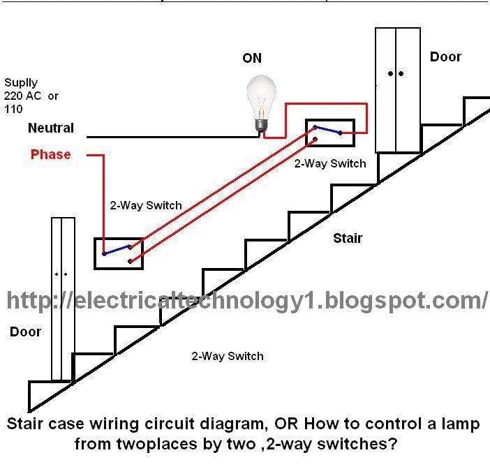
The circuit is complete, and the bulb is ON. To turn OFF the bulb from the upper switch at the top of the stairs, simply turn OFF the switch, which will break the circuit and turn the bulb OFF....
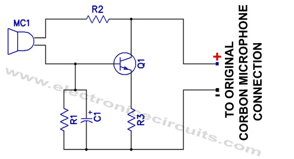
Effective pitching surpasses effective hitting, and a high-quality magnetic microphone outperforms a carbon microphone. This circuit utilizes a single transistor to convert a carbon microphone input into a magnetic microphone output. It is important to note that no ground...
Electronic potentiometer using a standard CMOS logic and analog multiplexers. Pot have low distortion (0.005% less at 1 V rms) and is it easy for beginners to understand. In the beginning, the art of Hi-Fi, in the absence of...
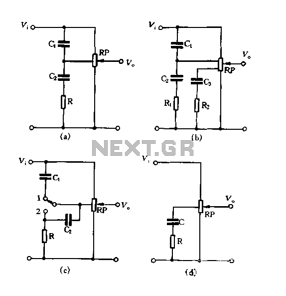
Figure 1.88 illustrates the loudness control circuit utilizing multiple taps on a potentiometer. In Figure (A), the connection is made between the tap and the potentiometer's input, along with the ground. An RC compensation network is employed, where the...