
Battery Replacement Power Supply

The proposed circuit design features a switchable power supply that can effectively replace battery cells in a variety of applications, especially in toys and portable devices. The core component of this design is the LM317T adjustable voltage regulator, known for its reliability and versatility in providing stable output voltages. The LM317T can output a voltage range that can be adjusted based on the needs of the circuit, making it suitable for powering devices that require different voltage levels.
The circuit includes six trimpots, which are variable resistors that allow for fine-tuning of the output voltage. These trimpots are connected to switch S1b, enabling the user to select the desired voltage output by adjusting the respective trimpot. This feature provides flexibility, allowing the user to cater to various devices that may require different operating voltages.
To optimize the performance of the LM317T and reduce heat generation, switch S1a is employed to select different taps from the transformer secondary. This selection is crucial as it helps to minimize the voltage drop across the regulator, thereby reducing power dissipation and improving overall efficiency.
The circuit also incorporates a diode (D1) for protection against reverse polarity, ensuring that the circuit components are safeguarded from potential damage. The inclusion of a 10 µF capacitor serves to stabilize the voltage output, filtering any high-frequency noise that might interfere with the operation of sensitive electronic components.
The LED indicator, powered through the circuit, provides a visual cue of the power status. Its design ensures constant brightness, which is a significant advantage over using an unregulated DC supply, where variations in voltage could lead to inconsistent LED illumination. This feature enhances the usability of the device, providing users with reliable feedback regarding the operational status of the power supply.
In summary, this switchable power supply circuit is a practical solution for temporarily replacing battery cells in electronic devices, particularly toys. Its design prioritizes efficiency, flexibility, and user feedback, making it an effective tool for both troubleshooting and powering various electronic applications.Your child`s battery toy has failed and you have to fix it. Once you have managed to get it apart, the battery compartment is not likely to be connected to the works or the batteries might have gone flat anyway. The solution is this switchable supply which is designed to replace from one to six dry cells. It is not intended to replace the batterie s on a permanent basis, as in most cases this is not practical. The heart of the supply is an LM317T adjustable 3-terminal regulator and six trimpots selected by switch S1b. The other pole of the switch, S1a, is used to select taps on the transformer secondary, to minimize power dissipation in the LM317T.
The table shows the trimpot settings for the six voltage outputs. Diode D1 and the 10 µF capacitor and the LED provide power indication. This has the advantage of constant brightness which would not be obtained if the LED was run from the unregulated switchable DC. 🔗 External reference
Related Circuits
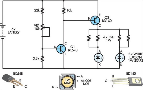
This circuit replaces two white Luxeon 1W Star LEDs for the inverter and fluorescent tube in a standard battery-powered illuminated exit sign, commonly found in commercial buildings. Although the Luxeon LEDs produce less light output than a typical small...
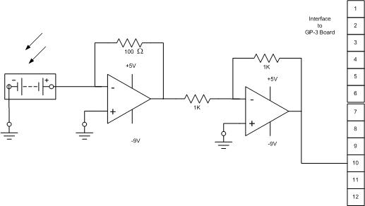
The solar cell used for the solar tracking experiment is made from crystalline silicon, with a maximum voltage rating of 55V and a maximum current rating of 300 mA. It can be purchased at local Radio Shack stores for...

The circuit functions as a constant voltage source, modified by feedback components R2 and R3 to maintain a stable output voltage. The ZN424E output must be at least 2 volts above the negative rail, with the load connected to...
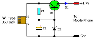
This simple circuit provides a regulated output of 4.7 volts for charging mobile phones. A USB outlet delivers 5 volts DC at a current of 100 mA, which is adequate for slow charging of mobile devices. Most mobile phone...
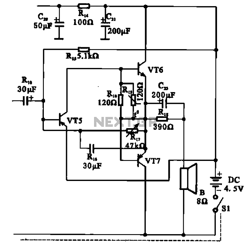
The transistor radio features a common output transformerless (OTL) power amplifier circuit. The VT5 component serves as the bias resistor for the driver stage. VT6 and VT7 form a complementary symmetry configuration, with VT6 being a germanium NPN transistor...
Zilog's Z8 Encore XP F1680 Series features a highly optimized set of capabilities specifically designed for stepper motor microstepping control. Key features of the Z8 Encore! XP F1680 include: an 11 MHz internal oscillator, two analog comparators, a 10-bit...