
pll fm circuit

The design of this FM transmitter circuit incorporates several critical components to achieve its functionality. The LMX1601 frequency synthesizer chip serves as the core of the PLL system, ensuring accurate frequency generation. The microcontroller, AT90S2313, facilitates communication with the LMX1601, allowing for dynamic adjustments to the PLL parameters via software.
The circuit layout includes the necessary power supply filtering to ensure stable operation of both the microcontroller and the LMX1601. Bypass capacitors are placed close to the power pins of the LMX1601 to minimize noise and improve performance. The VCO, which is not part of the LMX1601, must be selected based on the desired frequency range and characteristics, ensuring it can operate effectively within the constraints set by the PLL.
The output stage of the transmitter typically includes a buffer amplifier to ensure that the output signal is strong enough for transmission. This stage must be designed to match the impedance of the antenna used, commonly 50 ohms, to maximize power transfer and minimize reflections.
Additionally, the firmware controlling the AT90S2313 is programmed to handle user inputs for frequency adjustments, providing a user-friendly interface for tuning. The design should also incorporate safety features, such as over-temperature protection and output power limiting, to prevent damage to the components and ensure compliance with regulatory standards for FM transmission.
In summary, this circuit design represents a comprehensive approach to building a crystal-controlled low-power FM transmitter, integrating advanced frequency synthesis techniques with user-friendly controls and robust output characteristics. The use of modern components, such as the LMX1601, alongside established microcontroller technology, exemplifies the evolution of FM transmission design, allowing for precise and reliable operation in the FM broadcast band.The common characteristic of all of the previous low power FM transmitters I`ve built over the decades, is that their operating frequency is determined by an LC resonant circuit. Some of them had excellent stability, some of them didn`t, but I had always wanted to make one that is crystal controlled. Various schemes had been considered from time-to-time, including the direct approach of modulating the load capacitance of a a crystal oscillator, a whimsical phase modulation scheme involving a phase shifter, some balanced modulators, and limiting amplifiers, and at times, the down-to-earth and sober approach of modulating a VCO within a phase locked loop (PLL).
While browsing Digikey`s online catalog, I found the LMX1601 frequency synthesizer chip and thought: "Just maybe, the PLL approach is finally within my grasp. " The LMX1601, which apparently was designed for use in cell phones, includes everything need to make two phase locked loops except for the VCOs.
More importantly, one of the PLLs, specifically the "AUX" PLL, is specified to work in the FM broadcast band. The LMX1600 and the LMX1602 were also considered, but the LMX1601 was selected because it has a "500 MHz option", meaning that it can work down to about 50 MHz.
In order to function, the LM1601`s registers need to be loaded. In particular, they need to be loaded with the divide ratios for the reference and signal (VCO in this case) counters, and to set some control parameters. To load the registers, I used a Atmel AT90S2313. It could have been any microcontroller with 3 I/O pins, but I had chosen the AVR processor, and I still have a lot of AT90S2313 chips left over from another project.
To the best of my knowledge, the ATtiny2313 can be substituted without changing the source code. The 20 pin DIP appears monstrously large compared to the diminutive LMX1601. The size difference is an indication of the passing of the three of four decades that elapsed between the introduction of these two packages. The LMX1601 has a reference divider, which I used to divide the 4 MHz clock from the micro controller`s crystal oscillator, down to 12.
5 kHz reference frequency. The feedback divider, referred to as "16 Bit AUX N Counter" in the data sheet, is proceeded by a divide by 8 prescaler. These factors determine the channel spacing for the phase locked loop. 8 X 12. 5 kHz = 100 kHz. The AUX N register contains the divide ratio for the feedback divider, and the phase locked loop tries to make the VCO operate at a frequency equal to the value written to the AXU N register, times 100 kHz.
I say "tries" because the actual frequency of oscillation depends on the range of the VCO itself. This means that the center requency of the resulting frequency modulated oscillator can be set with 100 kHz resolution, enabling it to be set either on or between allocated FM broadcast channels throughout most of the world. If a value of 1000 is written into the AUX N register, the PLL will try to run at 100 KHz X 1000 = 100 MHz.
The math isn`t so hard, and I skipped the hard math -the loop gain and bandwidth calculations- so this should be an easy project, mathwise. In the firmware, an 8 bit count is used as the " channel " number. The highest frequency, which occurs when the channel number is 255, is set to 108 MHz by adding an offset of 825 to the channel number.
I did this because the part of the spectrum just above the FM broadcast band is used for aviation communications in most, if not all, parts of the world. When the frequency increment and decrement buttons are pressed, the channel number increments or decrements, respectively.
The button increment and decrement routines that limit the channel number to those that correspond to frequencies between 88. 0 Mhz and 108. 0 MHz. 🔗 External reference
Related Circuits
A highly accurate digital thermometer utilizing an LM35 probe with a resolution of 0.1 degrees Celsius. The circuit includes two adjustable components. The first, R5, is used to calibrate the display to zero. To perform this calibration, the end...
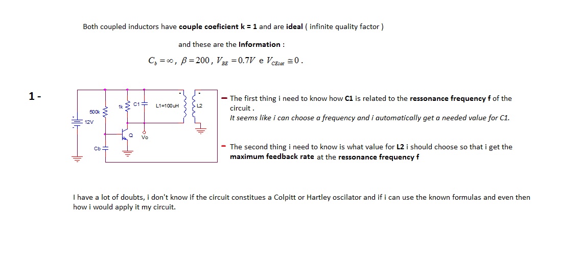
The first thing to understand is how capacitor C1 is related to the resonance frequency f of the circuit. It appears that selecting a frequency allows for the automatic determination of the necessary value for C1. There are uncertainties...
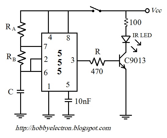
The remote control circuit comprises two main components: a transmitter and a receiver. The transmitter circuit is controlled by an NE555 integrated circuit (IC), while the receiver operates based on the frequency of the signal emitted by the transmitter....
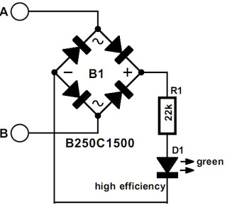
The modem off indicator is designed specifically for avid Internet users. The circuit for this indicator is remarkably simple, and its simplicity may lead to significant cost savings by providing a clear visual indication of whether the telephone line...
One of the critical components is a PWM speed controller, allowing for fine speed adjustments instead of just an "on" mode that runs at full power. This is important for safety. A basic stamp microcontroller was purchased, which includes...
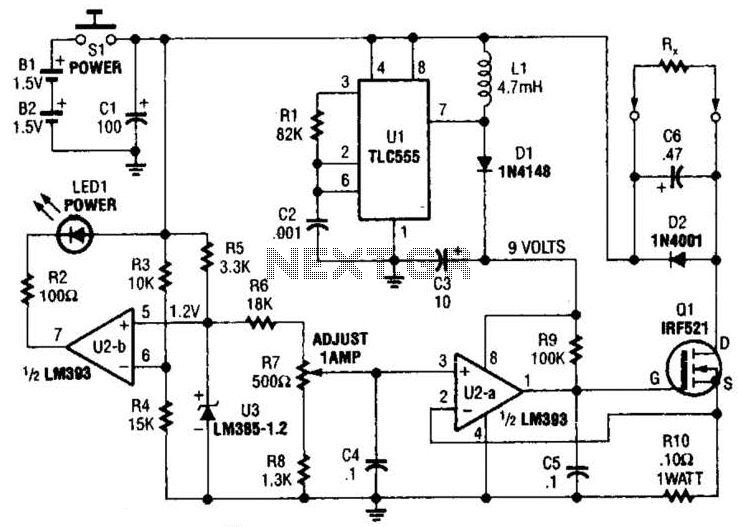
Useful for low-resistance measurements, this 1-A current source will produce 1 A in unknown resistance Rx. For best results, Rc should be less than 1 to 2, because only 3 V are available. Ul is a flyback converter to...