
PLL Hum Cancellation Circuit

A Phase Locked Loop (PLL) hum cancellation circuit is an advanced solution for mitigating unwanted noise in audio amplification systems, particularly in high-fidelity applications. The circuit architecture typically includes a phase comparator that detects the phase difference between the incoming line frequency and the output of the VCO. The loop filter smooths the control voltage derived from the phase comparator, ensuring stable operation of the VCO. The VCO generates a frequency significantly higher than the line frequency, allowing for precise control over the cancellation signal.
In this design, the division of the VCO frequency into 16 segments enhances the granularity of the phase adjustment, facilitating finer control over the amplitude and phase of the cancellation signal. Each of the eight trimmer potentiometers allows for individual tuning, enabling the user to compensate for specific characteristics of the residual hum. The summation of these signals produces a composite cancellation waveform, which is then filtered to remove any extraneous high-frequency noise that may adversely affect the audio output.
Injection points for the cancellation signal are critical to the performance of the circuit. Inserting the cancellation signal into the grid of a vacuum tube or the bias path of output tubes can significantly enhance the effectiveness of the hum cancellation. The design should ensure that the injection does not adversely affect the overall gain or frequency response of the amplifier.
The initial setup of the circuit requires careful attention to the voltage source used for the PLL. Ensuring that the input voltage is stable and correctly referenced to ground is essential for optimal operation. The adjustment process, as previously described, involves careful monitoring of the output signal and iterative tuning of the controls to achieve the desired hum reduction.
In summary, the PLL hum cancellation circuit represents a sophisticated approach to addressing residual hum in audio amplifiers, leveraging phase-locked technology to provide a versatile and effective solution for enhancing audio fidelity. Proper implementation and adjustment of the circuit can lead to significant improvements in the listening experience, particularly in high-performance audio systems.This report describes the operation and adjustment of a Phase Locked Loop hum cancellation circuit that can be used to reduce the residual hum from any amplifier. Normally this is useful for DHT amplifiers with AC operated filaments, as even with a hum balancing potentiometer, there is a residual hum component at twice the line frequency that is u
navoidable, even with perfectly filtered HT voltage. However, it may be applied to any amplifier. I`ve reported a hum cancellation circuit (here) that provided improvement in hum performance of many DHT circuits. Some people have used this successfully, some with only limited success. The key is to get the amplitude and phase set just right to cancel the residual hum component. This is not always easy nor convenient, so I sought a way to make this concept more universally applicable.
This report describes the results. The key behind this version is the use of a phase locked loop, fed from the mains supply (50 or 60 Hz). A PLL consists of a phase comparator, a loop filter and a voltage controlled oscillator (VCO). The phase comparator compares the phase and frequency of an incoming signal (the line frequency, not the "music" source) against an oscillator, and adjusts the oscillator frequency so that it equals the incoming reference.
In this case, the VCO operates at 16 times the line frequency (800 or 960 Hz), which is divided by 16 and compared to the line frequency. The x16 allows the line to be split into 16 equal portions. For simplicity, I opted to split this into 8 equal portions, each of which separately control a trimmer pot.
The portions are summed and filtered to produce a cancellation signal that can be used to compensate for an arbitrary phase and amplitude of the residual hm signal to be canceled. The filter removes any higher order components, so that more audible, but lower amplitude higher order components are not introduced into the amplifier.
The "injection" into the main amplifier may be at any convenient point. In the 845 amp, it is introduced into the otherwise "unused" grid of the upper tube of the cascode stage. It may also be introduced into the output tubes bias path. For details on how to do this, see the first hum balancing report. (here). First build the circuit, and attach the inputs (upper left in the schematic) to a 6. 3 volt source. This may be a 6. 3V winding with one side grounded, or a 6. 3 volt CT winding where the center tap is grounded. If the latter, the attachment is one side (either side) of the 6. 3 and ground. (This will place 3. 15VAC on the circuit which is sufficient). The first adjustment is to set the VCO frequency, shown in the schematic as "lock PLL". This will be near minimum resistance with 60Hz mains, and near maximum resistance with 50Hz mains. If you have a scope, you will see that pin 3 of the `4046 is at the same frequency as the mains. A main level control and a set of 8 amplitude-phase controls is used for the channel. First, set one of the 8 A-P controls at one end of the control, and the other 7 at the other end of the control, and the main level control about "half way up".
If you have a scope, you should be able to see a sort of peaky signal at line frequency at the output. (hum bal ch1 or hum bal ch2). If you don`t have a scope, you should be able to see a few hundred millivolts of signal on an AC voltmeter.
Now turn the main level control all the way down, and connect it into your amplifier circuit. Then turn on the amp and slowly advance the main control. The hum at the amplifier output should either go up (according to Murphy`s law, it will go up) or down. Continue advancing the control until the hum is about 6 dB stronger (or 6dB weaker) than it was without the system connected.
Now, sequentially adjust the 8 A-P controls for minimum hum. You will have to repeat this sequence a few times. If you get to the point where you want more range on the A-P pots, s 🔗 External reference
Related Circuits
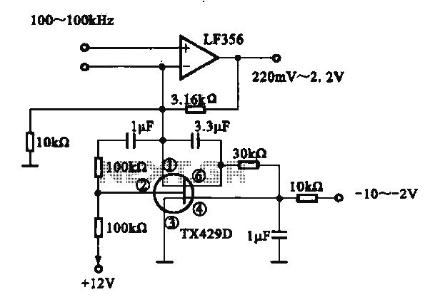
A variable gain amplifier is presented. This circuit adjusts the output signal amplitude based on the input signal. The core component is an operational amplifier configured with a negative feedback circuit. By varying the feedback amount, the gain of...
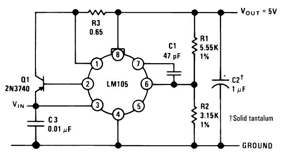
A single diffused, wide base transistor, such as the 2N3740, is recommended due to its reduced tendency to cause oscillation issues compared to double diffused, planar devices. Additionally, it exhibits greater reliability under overload conditions, and low-cost options are...
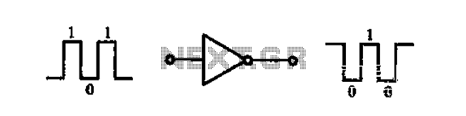
A common-emitter transistor amplifier produces an output signal that is 180 degrees out of phase with the input signal, commonly referred to as an inverting amplifier. When the electrical path for amplifying the pulse signal is activated, this circuit...
A battery-status indicator circuit is useful for monitoring portable test equipment and similar devices. LED D1 flashes to attract the user's attention, signaling that the circuit is operational, preventing it from being left on unintentionally. The circuit produces approximately...
The synchronous vibration circuit operates with a control logic that includes three primary components. An internal oscillator is initiated by a synchronization pulse, transitioning to a low state immediately after the pulse. Upon power activation, the internal circuitry undergoes...
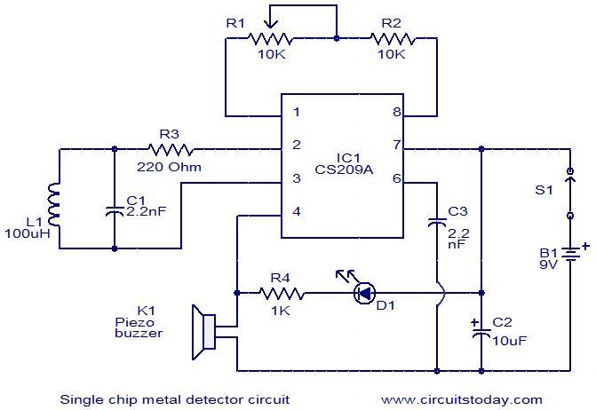
This is a simple single-chip metal detector circuit based on the IC CS209A from Cherry Semiconductors. A 100µH coil is utilized to detect the presence of metal. The IC CS209A incorporates a built-in oscillator circuit, with the coil (L1)...