
Flashing-LED Battery-Status Indicator Circuit

The battery-status indicator circuit is designed to provide a clear and efficient method for monitoring battery levels in portable electronic devices. The astable multivibrator configuration utilizing Q1 and Q2 allows for a low-power operation, which is crucial for battery-powered applications. The flashing LED serves as an effective visual cue, ensuring that users are aware of the circuit's operational state.
The choice of using a Schottky diode for D1 is critical due to its low forward voltage drop, which minimizes the impact on the overall voltage level sensed by the circuit. This ensures accurate detection of the battery voltage and timely alerts to the user regarding battery status. The ability to adjust the threshold voltage with Trimmer R4 provides flexibility in tailoring the circuit to different battery types and capacities, enhancing its versatility across various applications.
In practical applications, the circuit can be integrated into devices such as handheld multimeters, portable oscilloscopes, or any battery-operated test instruments where monitoring battery life is essential. The design considerations, including the selection of component values for R3 and R4, should be made based on the specific requirements of the intended application to optimize performance and reliability.
Overall, this battery-status indicator circuit is a well-thought-out solution for ensuring users are informed about battery conditions, thereby preventing unexpected device shutdowns due to low battery levels.A Battery-status Indicator circuit can be useful, mainly to monitor portable Test-gear instruments and similar devices. LED D1 flashes to attire the user`s attention, signaling that the circuit is running, so it will not be left on by mistake.
The circuit generates about two LED flashes per second, but the mean current drawing will be about 200 µA . Transistors Q1 and Q2 are wired as an uncommon complementary astable multivibrator: both are off 99% of the time, saturating only when the LED illuminates, thus contributing to keep very low current consumption. The circuit will work with battery supply voltages in the 5 12V range and the LED flashing can be stopped at the desired battery voltage (comprised in the 4.
8 9V value) by adjusting Trimmer R4. This range can be modified by changing R3 and/or R4 value slightly. When the battery voltage approaches the exhausting value, the LED flashing frequency will fall suddenly to alert the user. Obviously, when the battery voltage has fallen below this value, the LED will remain permanently off.
To keep stable the exhausting voltage value, diode D1 was added to compensate Q1 Base-Emitter junction changes in temperature. The use of a Schottky-barrier device (e. g. BAT46, 1N5819 and the like) for D1 is mandatory: the circuit will not work if a common silicon diode like the 1N4148 is used in its place.
🔗 External reference
Related Circuits

This is a solar charger circuit designed to charge Lead Acid or Ni-Cd batteries using solar energy. The circuit captures solar energy to charge the batteries. The solar charger circuit typically consists of several key components, including a solar panel,...

ETl3X220 is a cost-effective single-chip transmitter that operates via RF communication. It supports up to 10 channels and is ideal for applications such as wireless mice, keyboards, and other communication devices. The main technical features include: - Analog FM...

The schematic diagram of a microphone preamplifier is based on the operational amplifier TC251. The TC251 operates with low bias and functions with a supply voltage of only 1.5 V, drawing an electric current of just 10 mA, making...
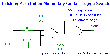
This page presents soft power switch circuits designed for toggling electronic devices ON and OFF with a momentary button press that controls a latching high-side MOSFET power switch. Multiple micropower latching switch circuits are included. Due to their low...

When the water level is low, the wires in the tank are open-circuited, causing the 180K ohm resistor to pull the switch low, resulting in the switch being open and the LEDs being off. As water begins to fill...
The circuit depicted in the figure is designed for multi-temperature testing, allowing for the switching of the thermocouple corresponding to the active channel. At the core of this design is a 555 timer configured in a monostable delay mode....