5W Chinese PLL FM Transmitter With LCD Printed Circuit Board (PCB)
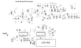
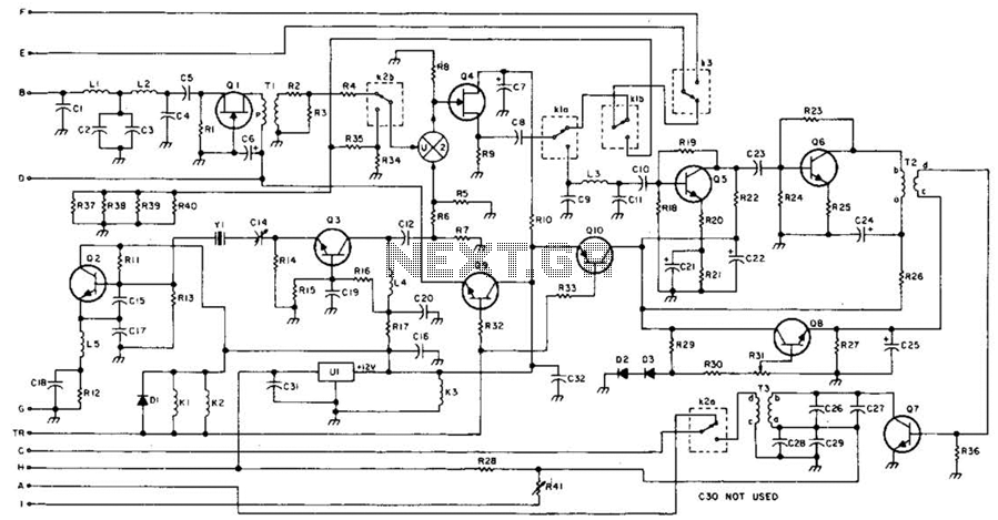
Here's PLL FM transmitter circuit from china. This circuit uses the familiar 2SC1971 for final power amplifier stage. The PLL controller of the FM transmitter use SAA1057 and PIC16F628 (download HEX file). More: If want to change the active component, here's the list: 2SC2458 = BC547 2SA1048 = BC557 2SK192 = J310 2SB562 = BD136, BD138, BD140 2SC1923 = BF199 of BRF91 2SC1923 = BF199 or BRF91 2SC2053 = BRF96 2SB1135 = BD136, BD138, BD140 MV2105-09 = BB105, BB119 Printed Circuit Board (PCB) for this FM transmitter circuit is 155 mm x 120 mm. All coils are 0.8 mm copper wire with a 6 mm diameter. Please see parts used from schematic.
The PLL FM transmitter circuit described utilizes a phase-locked loop (PLL) architecture, which is essential for maintaining frequency stability in FM transmission. The core of this circuit is the SAA1057 PLL controller, which is responsible for frequency modulation and demodulation processes. The choice of the PIC16F628 microcontroller allows for additional programmability and customization of the transmitter's functions, enhancing its versatility in various applications.
The final power amplification stage employs the 2SC1971 transistor, known for its robust performance in RF applications. This transistor is capable of delivering sufficient output power to effectively drive the antenna, ensuring a clear signal over a considerable distance.
For flexibility in component selection, a list of alternative transistors is provided, allowing designers to substitute with equivalent parts such as BC547 for 2SC2458 or BD136 for 2SB562, among others. This adaptability can be particularly useful in regions where specific components may be difficult to source.
The printed circuit board (PCB) dimensions are specified as 155 mm by 120 mm, which provides a compact form factor suitable for various installation scenarios. The design incorporates coils made from 0.8 mm copper wire wound to a diameter of 6 mm, which is critical for achieving the desired inductance values necessary for the oscillator and filter stages of the transmitter.
Overall, this PLL FM transmitter circuit is designed to be user-friendly while offering a range of customization options through component substitution, making it a practical choice for both hobbyists and professionals in the field of electronics.Here's PLL FM transmitter circuit from china. This circuit uses the familiar 2SC1971 for final power amplifier stage. The PLL controller of the FM transmitter use SAA1057 and PIC16F628 (download HEX file). If want to change the active component, here's the list: 2SC2458 = BC547 2SA1048 = BC557 2SK192 = J310 2SB562 = BD136, BD138, BD140 2SC1923 = BF199 of BRF91 2SC1923 = BF199 or BRF91 2SC2053 = BRF96 2SB1135 = BD136, BD138, BD140 MV2105-09 = BB105, BB119 Printed Circuit Board (PCB) for this FM transmitter circuit is 155 mm x 120 mm. All coils are 0.8 mm copper wire with a 6 mm diameter. Please see parts used from schematic. 🔗 External reference
