
portable mixer block diagram

The described mixer circuit is structured to optimize audio signal processing with a focus on low power consumption and high fidelity. The four input amplifier modules serve to boost the signals from various audio sources, ensuring that they are at an appropriate level for further processing. Each of these modules is designed to handle specific input types, including dynamic and condenser microphones, as well as line-level signals, providing versatility in audio mixing applications.
The four switchable tone management modules allow for the adjustment of tonal characteristics for each input channel, enabling the user to tailor the sound to their specific requirements. These modules can apply equalization, filtering, and other effects, enhancing the overall audio quality. The inclusion of a stereo line input further broadens the mixer's capabilities, allowing for the integration of external audio devices.
The main faders, including both mono and dual-ganged stereo configurations, provide precise control over the audio levels of each channel. The pan pots facilitate the spatial placement of audio signals within the stereo field, giving the mixer additional creative control. The stereo main mixer amplifier module combines all processed signals and amplifies them for output, ensuring a robust final mix.
The additional tone management modules before the main outputs are crucial for final adjustments, allowing for a last-minute enhancement of the audio signal before it is sent to the output stage. This modular approach not only enhances flexibility but also allows for easy upgrades or modifications to the mixer setup.
The circuit's low-noise and symmetrical design are particularly beneficial for professional audio applications, where signal integrity is paramount. The use of a two-transistor head amplifier layout minimizes distortion and noise, while the integration of a FET input operational amplifier as the second gain stage ensures compatibility with sensitive microphone inputs. This thoughtful configuration results in a mixer that is not only efficient in power usage but also capable of delivering high-quality audio performance across a wide range of applications.The image below shows a Block diagram of the entire mixer that includes four Input Amplifier Modules followed by four in-out switchable Tone management Modules, one stereo Line input, four mono Main Faders, one stereo dual-ganged Main Fader, four Pan-Pots, a stereo Main Mixer Amplifier Module and two additional Tone management Modules switchable i n and out for every channel, inserted before the main Left and Right outputs. Obviously this layout is rearranged at everyone want. An astonishing feature of this design lies within the fact that a whole stereo mixer as shown below within the Block diagram attracts but 6mA current! The basic arrangement of this circuit comes from the recent Quad magnetic pick-up cartridge module. The circuit was rearranged to address microphone input and a single-rail low voltage provide. This low-noise, absolutely symmetrical, two-transistor head amplifier layout, allows the utilization of a traditional FET input Op-Amp as the second gain stage, even for terribly sensitive microphone inputs.
🔗 External reference
Related Circuits
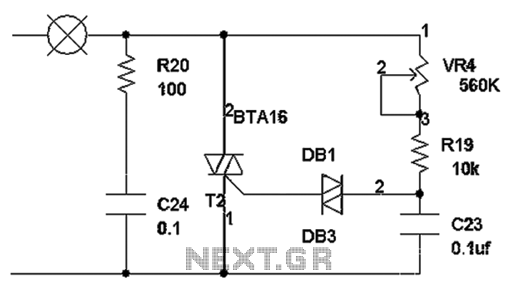
The TRIAC dimmer circuit diagram operates on the principle that a 220V lamp is controlled through the charging of capacitor C23 via resistors VR4 and R19. The charging time is influenced by the values of VR4 and R19, where...
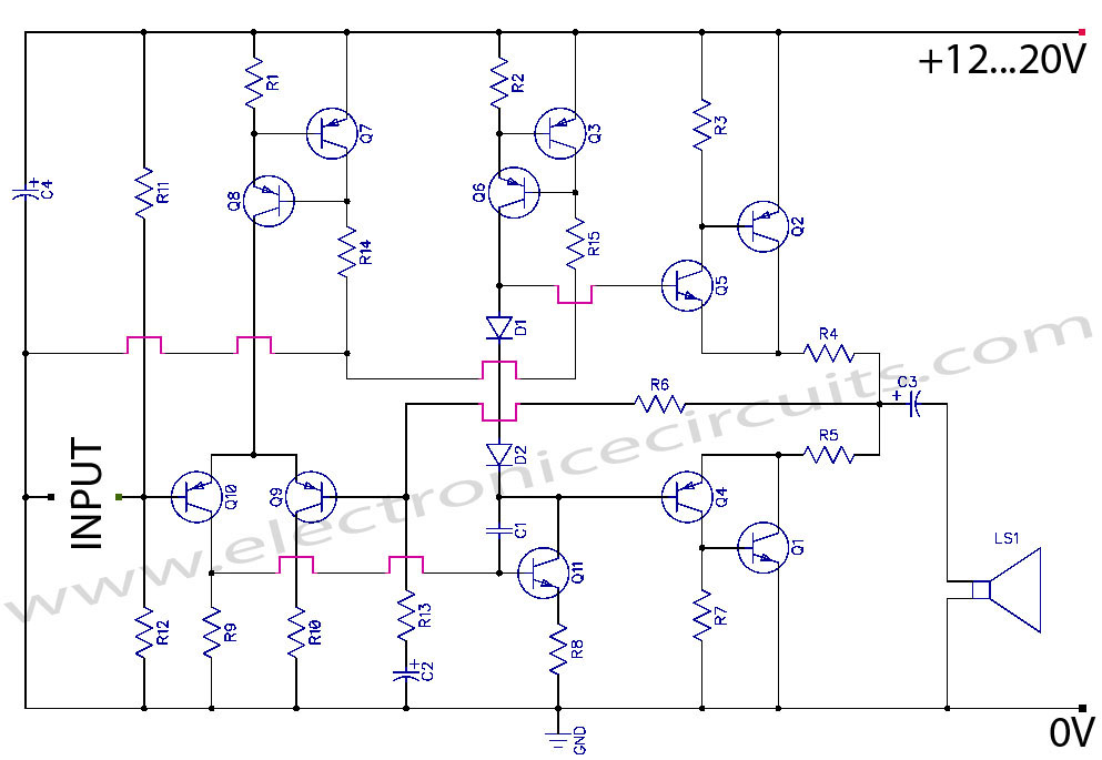
Discrete Class AB Transistor Audio Power Amplifier Circuit Diagram. This is a Class AB transistor power amplifier. It is a simple amplifier to... A Class AB transistor audio power amplifier is designed to provide high-quality amplification for audio signals while...
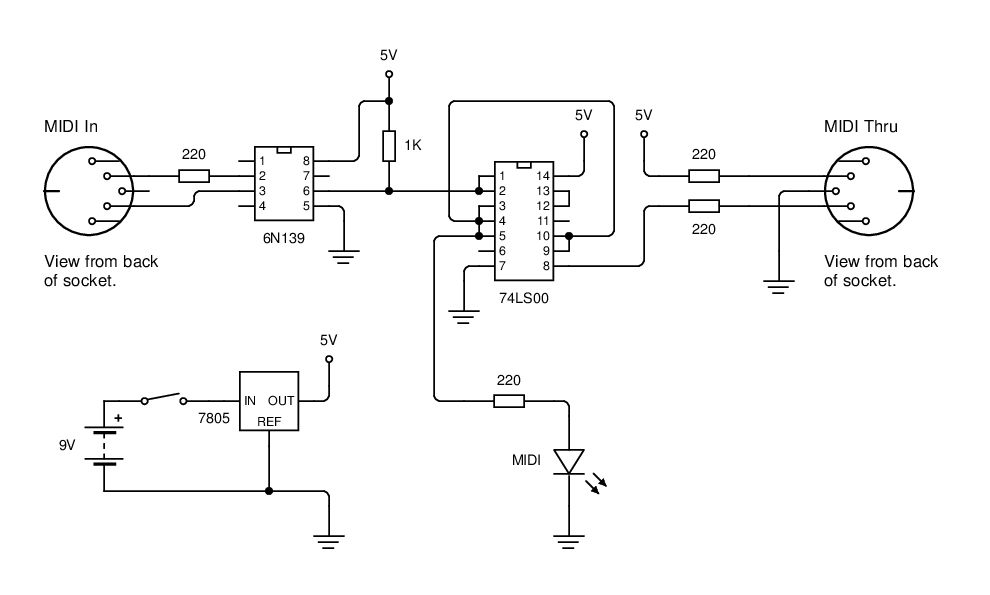
MIDI data is transmitted between instruments using a current loop, and an opto-isolator (6N139) is employed to convert this current loop into TTL pulses. The circuit utilizes the 6N139 opto-isolator to separate the MIDI signal from the receiving device, ensuring...
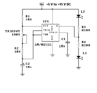
This is a simple LED flasher project that utilizes a common 555 timer integrated circuit (IC) for its operation. It is configured in astable mode, which means its output functions as a square wave oscillator. Two LEDs are connected...
This easy electronic buzzer circuit is built based on a timer that operates to generate frequency. The IC timer NE555 is used as an astable multivibrator operating at approximately 1 kHz, producing a sound when powered on. The sound...
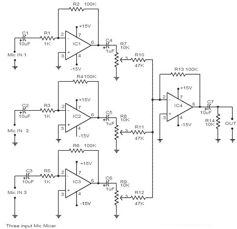
This is a circuit diagram of a 741 IC-based three-input microphone mixer circuit. A total of four 741 ICs are utilized, with IC1, IC2, and IC3 serving specific functions within the design. The circuit utilizes four operational amplifiers from the...