
Electronic Buzzer with IC timer NE555 circuit diagram

This electronic buzzer circuit utilizes the NE555 timer IC in an astable configuration to produce a continuous square wave output. The frequency of oscillation is primarily determined by the values of two resistors and a capacitor connected to the timer. In this configuration, the NE555 operates as a multivibrator, generating a square wave signal at a frequency of about 1 kHz, which corresponds to a tone audible to the human ear.
To adjust the frequency of the generated sound, a 10K resistor is used in the circuit. This resistor can be replaced with a variable resistor (potentiometer), allowing for fine-tuning of the sound frequency. By changing the resistance, the charging and discharging times of the timing capacitor are altered, thus varying the frequency of the output waveform.
The circuit typically includes a power supply, the NE555 timer IC, a timing capacitor, and the adjustable resistor. Upon powering the circuit, the NE555 generates a square wave output, which can be connected to a small speaker or piezo buzzer to produce sound. The output sound is a result of the rapid switching of the voltage levels, creating audible tones.
Overall, this buzzer circuit is simple and effective for applications requiring sound alerts or notifications, making it suitable for various electronic projects and prototypes.This easyelectronicbuzzercircuitbuilt based on timer works for gaining the frequency. The IC timer NE555 used as astable multivibrator operating at about 1kHz and produces a sound when switched on. The sound frequency can be adjusted by varying the 10K resistor. You may change the 10K resistor with variable resistor. We aim to transmit more infor mation by carrying articles. Please send us an E-mail to wanghuali@hqew. net within 15 days if we are involved in the problems of article content, copyright or other problems. We will delete it soon. 🔗 External reference
Related Circuits
The RF power amplifier circuit described here utilizes the transistors 2SC1970 and 2N4427. This FM RF amplifier operates within the frequency range of 88-108 MHz, delivering an output power of approximately 1.3W from an input driver of 30-50mW. The...
This circuit is designed for alerting purposes after a specified duration has elapsed. It is suitable for table games that require a fixed time limit to answer a question or to move a piece, serving as a modern substitute...
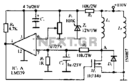
The LM339 comparator IC (Integrated Circuit) is utilized to enhance the functionality of electric circuits. A potentiometer (B) is incorporated to adjust the desired setpoint, while a feedback signal is generated by resistor (R). A significant pressure point is...
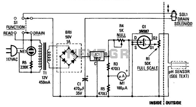
The drain-to-source resistance of Q1 varies depending on the acidity of the sample presented to Q1's gate circuit. This variable resistance influences the current flowing through the bridge, which is proportional to pH. The circuit involves a field-effect transistor (FET),...
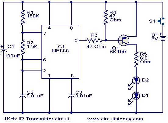
This circuit was designed in response to a request for a 1 kHz infrared (IR) transmitter circuit suitable for remote control applications. It is intended to serve as a low-power IR transmitter with an operating frequency of 1 kHz,...
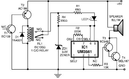
This heat detector alarm electronic project is designed using the UM3561 sound generator circuit along with several common electronic components. The heat detector circuit employs a complementary pair of transistors, consisting of an NPN and a PNP transistor, to...