
Portable Solar Powered Lantern Circuit

The circuit design utilizes a 5W/6V solar panel as the primary energy source, capable of providing a peak current of 800mA under optimal sunlight conditions. To maximize efficiency, the system can be designed to operate at a lower current draw, ideally around 150mA, although this may not fully utilize the panel's capacity. A more practical approach would involve integrating a 1W solar panel, which can deliver approximately 160mA during peak sunlight hours for a duration of 6 hours. This allows for flexibility in design, particularly in applications where energy consumption needs to be minimized.
For the lighting component, a series configuration of two LEDs per string can be employed, with ten strings connected in parallel. Each string operates at 8mA, resulting in a total current draw of 80mA. This configuration not only enhances brightness but also ensures that the system remains within the operational limits of the solar panel and battery. The total light output from this arrangement can reach approximately 100 lumens, with each LED contributing between 4 to 5 lumens. To optimize performance, a current-limiting resistor can be added in series with each string to fine-tune the brightness, potentially increasing the output to 6 lumens per LED.
The incorporation of an SPST switch allows for manual control of the circuit, enabling the user to turn the system on or off as needed. However, care should be taken to minimize the number of components in the circuit to avoid excessive voltage drops and power loss, particularly through resistors. A well-designed circuit should balance the number of components with the desired performance, ensuring that the overall system remains efficient and cost-effective while providing reliable illumination.The panel 5W/6v Wp will have a max current of approx 500 to 800mA peaking at 800mA at noon. by restricting it to 150mA seems sheer waste. you can use a 1W panel to provide you 160mA at peak performance of 6 hours, to cover for the worst case scenario maybe 2W would be fine. thus reducing the cost of the panel. The 1W LED will give approx 80 to 1 00 Lumens this can be provided by use of a series of 2 LED`s in a strings and have 10 strings each string @8mA for Ultra brightness so the consumption is reduced to 80mA. the battery would last for 6 hours providing illumination of approx 100 Lumens (each LED @4/5 Lumens and you can get 6 Lumens by adding a current limiting resistor in series with each string Too many components after the SPST warming the circuit wasting it in the 5W resistors
🔗 External reference
Related Circuits
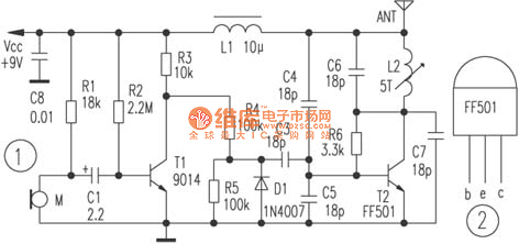
The circuit depicted utilizes a specialized launch tube T2 along with its associated components to create a high-frequency oscillator operating within the frequency range of 88 to 108 MHz. An electret microphone captures the audio signal, which is subsequently...
The previous version of this device used pulse width modulation (PWM) to control the power from the five solar panels to charge the battery bank. Under full sun conditions, the MOSFETs got a bit warm and the whole unit...
The contact resistance measuring circuit is illustrated in the figure. It primarily consists of a constant current circuit and an amplifying circuit. Operational amplifier IC1 is configured as a voltage follower, and the voltage across the load equates to...
The LM317 is an adjustable, positive 3-terminal voltage regulator capable of supplying 100 mA (for RA87U control) or 1.5 A (for Order Code UF27E and N61CA) across an output voltage range of 1.2 V to 37 V. These voltage...
This LED flasher circuit is a classic two-transistor flip-flop. It is a popular circuit often built by beginners in electronic circuit design. The schematic diagram of this well-known LED flasher circuit consists of two transistors, two capacitors, four resistors,...

The PGA202 offset voltage correction circuit is designed to correct both input and output offset voltages. There are four different gain settings for the PGA202, which result in slight variations in input offset voltage. A 50k potentiometer is used...