
Long-range FM radio transmitter circuit

The described circuit functions as a basic RF transmitter capable of modulating audio signals for wireless transmission. The electret microphone serves as the primary audio input, converting sound waves into electrical signals. The role of transistor T1 is critical as it amplifies these signals, ensuring that the modulation process can effectively alter the carrier wave produced by the oscillator circuit formed around tube T2.
The high-frequency oscillator is essential for generating the RF signal within the specified FM broadcast band. The choice of the FF501 tube is notable for its reliability and performance in RF applications, making it suitable for this type of circuit. The TO-92 package allows for easy integration into various circuit designs while maintaining a compact form factor.
When the microphone is not in use, the circuit can seamlessly switch to a cassette player input, broadening its functionality to include music transmission. This versatility is advantageous for applications such as personal FM transmitters or small-scale broadcasting setups.
The circuit's design emphasizes adjustability, allowing the user to fine-tune the output frequency and modulation characteristics to optimize performance. The output power of the RF signal is also a crucial consideration, as it determines the effective transmission range. By leveraging the properties of the FF501 tube, the circuit can achieve a robust output suitable for various transmission needs.
Overall, this RF transmitter circuit exemplifies a straightforward yet effective design for audio transmission, combining essential components to achieve reliable performance in the FM frequency range.In the circuit shown, the special launch tube T2 and its peripheral parts form a high-frequency oscillator with frequency in the range of 88 ~ 108MHz. The electret microphone picks up the audio signal, then the signal is amplified by T1, then the amplified low frequency signal makes modulation for high-frequency carrier.
If the electret microphone M disconnects, the input end connects cassette player, and it can transmit music. The RF transmitter dedicated tube T2 chooses FF501 which uses a standard T0-92 package (like the 9000 series of transistors ), shape, and pin arrangement is shown in Figure 2. The dedicated tube has the advantages of good consistency, the RF output power is greater, and the circuit is easy to adjust, and the FF501 also can work at a higher frequency band.
🔗 External reference
Related Circuits
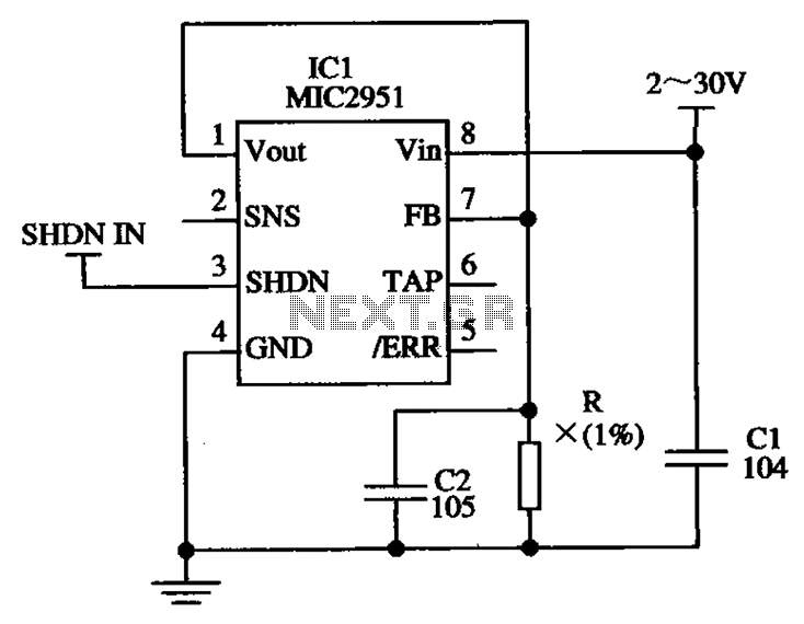
The circuit illustrated in the figure utilizes the low-drift current source circuit MIC2951, which is designed to provide specific output current values. The MIC2951 is a precision voltage regulator that can also be configured to function as a low-drift current...
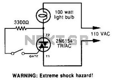
A triac can be utilized as a line-operated AC power switch that directly controls lamps, heaters, or motors. A brief current pulse into the gate activates the triac, and it remains on until the main current reverses. A triac, or...
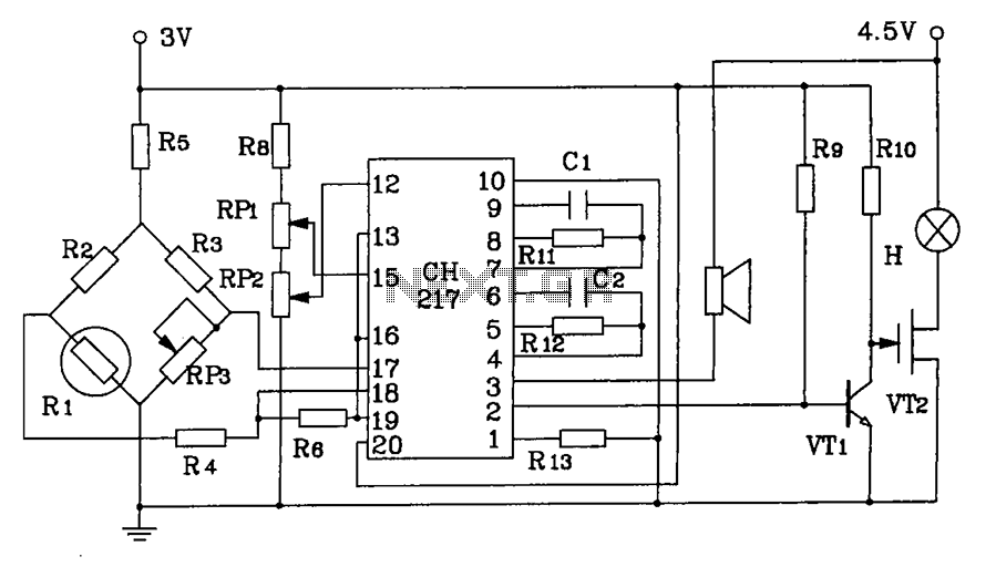
CH217 is a monolithic gas detection alarm integrated circuit. The gas detection alarm circuit diagram includes R1 as the gas sensing probe, where the resistance increases as the gas concentration decreases linearly. RP3 is used to adjust the output...

A 12 V car battery can be utilized as the 12 V input power source. The potentiometer R1 can be adjusted to achieve a 50 Hz output frequency. It is recommended to use a 10 A fuse in series...

A remote control light switch designed to fit into an existing light switch panel requires a 3.3V DC power supply for its electronics. However, the panel contains only two wires: one live wire and one wire that connects to...

Currently, the use of cookers has become fashionable due to their speed, cleanliness, and low pollution levels, making them a favorite among consumers. Cookers circuit. The modern cooker circuit typically involves a combination of heating elements, control systems, and safety...