
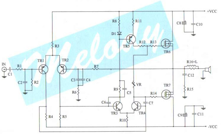
power amplifier 60w

The circuit is a product of the technological advancements of the 1980s, characterized by its robust design and reliability. It incorporates a straightforward architecture that ensures stable performance over time. The power supply section is crucial, as it must provide a consistent voltage and current to the circuit. Careful selection of components, such as capacitors and voltage regulators, is necessary to maintain the integrity of the power supply under varying load conditions.
The heatsink is another critical component, as it dissipates heat generated by the circuit during operation. An inadequate heatsink can lead to overheating, which may compromise the performance and longevity of the circuit. The selection process involves calculating the thermal resistance required to keep the junction temperature of the transistors within safe limits, taking into account the maximum power dissipation.
Driver transistors play a vital role in interfacing different sections of the circuit. Proper matching of these transistors ensures optimal signal integrity and minimizes distortion. The circuit design should consider parameters such as the current gain and switching speed of the transistors to achieve the desired performance.
Overall, the circuit reflects the engineering principles of its time, emphasizing reliability, efficiency, and ease of maintenance. It serves as a testament to the design practices of the 1980s, showcasing how thoughtful design considerations can lead to enduring performance.This circuit was designed and manufactured the `80`s. From then it works without problem. It does not present any particular constructional problem, beyond known: the attention in the provided force of power supply - choice suitable heatsink and good matching of drivers transistor.. 🔗 External reference
Related Circuits
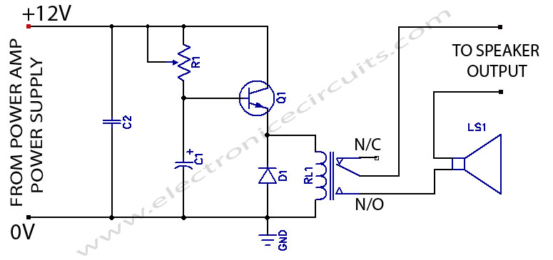
When powering on a power amplifier, a loud thump sound occurs due to a sudden heavy discharge current through the speaker. This current has the potential to damage the speaker, particularly in the case of a direct-coupled amplifier. The phenomenon...
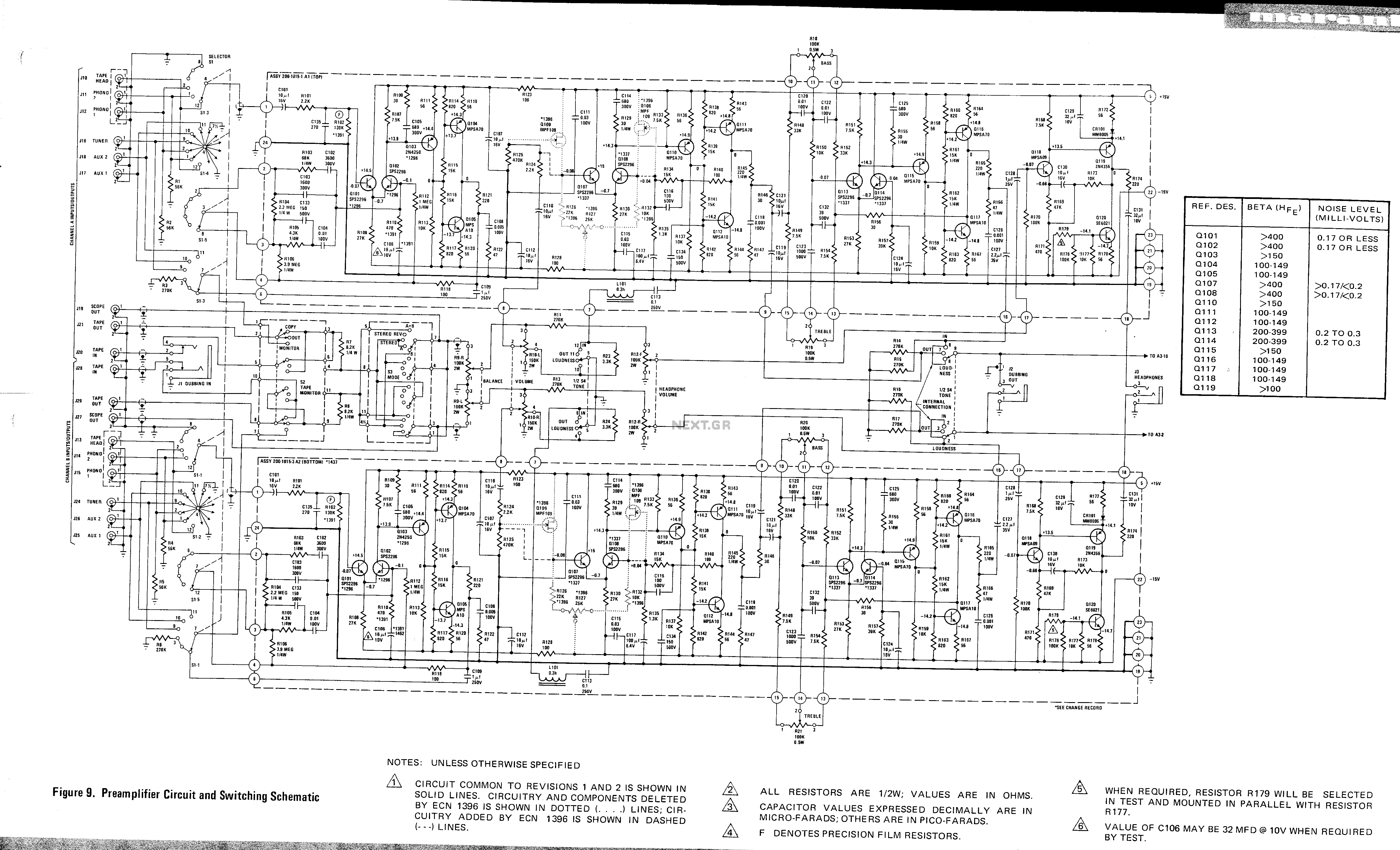
This is a preamplifier circuit and switching schematic for the Marantz Model 33. The Marantz Model 33 preamplifier circuit is designed to amplify low-level audio signals from various sources before sending them to a power amplifier. The schematic typically includes...
This complete aerial quality, low noise address audio amplifier is based on the Hybrid Integrated Circuit STK4050 manufactured by Sanyo. The circuit incorporates all necessary components and has a maximum output power of 200W. It features an onboard power...
The main part of this circuit is the LM386 amplifier chip. It also uses a transistor input to buffer the input signal and provide extra gain for the LM386. The little unit has helped me out on numerous occasions...
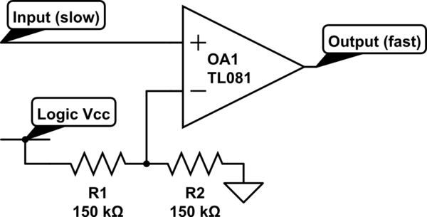
Invert a signal to drive FETs with rapid rise and fall times. It was suggested to use an inverter (not a chip) instead of logic chips, which are designed to be either fully ON or OFF. The individual has...
The schematic diagram of a 100-watt audio amplifier utilizing MOSFET technology. A comprehensive collection of electronic circuit diagrams is available, including a 100W RMS amplifier and a 0-30V stabilized variable power supply with current control. The 100-watt audio amplifier schematic...