
Marantz Model 33 Preamplifier circuit and switching schematic

The Marantz Model 33 preamplifier circuit is designed to amplify low-level audio signals from various sources before sending them to a power amplifier. The schematic typically includes several key components such as operational amplifiers, resistors, capacitors, and switches to facilitate signal routing and gain control.
The circuit begins with input connectors that receive audio signals from sources like turntables, CD players, or other audio devices. From there, the signals pass through a series of capacitors that block any DC offset while allowing AC audio signals to pass. This is crucial for protecting downstream components from potential damage caused by DC voltages.
Operational amplifiers (op-amps) are central to the amplification process. They are configured in a non-inverting or inverting arrangement, depending on the desired gain characteristics. Feedback resistors are employed to set the gain of the op-amps, ensuring that the output signal is appropriately amplified without distortion.
Switching elements, such as toggle or rotary switches, are included in the schematic to allow users to select between different input sources. These switches may also provide options for adjusting the tonal quality of the audio signal, such as bass and treble controls.
Output capacitors are used to couple the amplified signal to the power amplifier while blocking any DC components. This ensures that only the amplified AC audio signal is transmitted to the next stage in the audio chain.
Overall, the preamplifier circuit for the Marantz Model 33 is engineered to provide high fidelity audio performance, characterized by low noise and minimal distortion, making it suitable for audiophiles and music enthusiasts. Proper layout considerations in the PCB design, including grounding and shielding, are essential to maintain signal integrity and minimize interference from external sources.This is a Preamplifier circuit and switching schematic for Marantz Model 33. 🔗 External reference
Related Circuits
A simple and cost-effective TV antenna amplifier circuit is constructed using the BF961, a dual-gate N-channel MOSFET, which serves as the input and mixer stages. The described TV antenna amplifier circuit utilizes the BF961 dual-gate N-channel MOSFET due to its...

To invoke the Spectrum +3 diagnostic routines, first reset the machine while holding the BREAK key down. This will bring up the test card display. Next, hold down the QAZMLP keys for a few seconds until the diagnostic title...
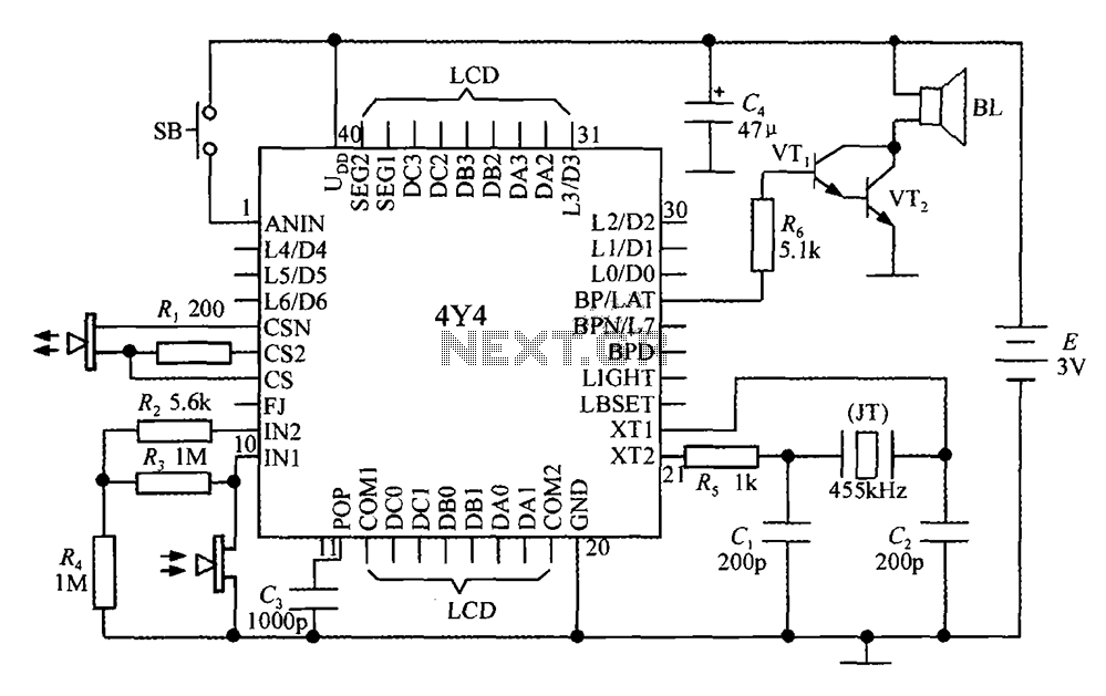
The 4Y4 is a monolithic liquid crystal display rangefinder circuit. The instrument comprises an ultrasonic transmitter, a receiver, an LCD display, buttons, switches, and a buzzer (or speaker). To simplify wiring, the 4Y4 is directly welded to the back...
Radio Control Circuits PDF Manual Download. This document serves as a comprehensive guide to radio control circuits, intended for individuals seeking to understand the principles and applications of radio frequency (RF) technology in controlling various devices. The manual covers fundamental...

A 40673 dual-gate MOSFET is matched to a crystal filter operating at 45 MHz. The filter impedance is approximately 2 kΩ. The +4 V source can be adjusted to control the gain, ranging from +4 V to -4 V. The...

An FM radio generates an interference signal that can be detected on another FM radio tuned 10.7 MHz higher than the original. A 50 kΩ potentiometer is used to adjust the modulation level to its maximum without introducing distortion....