
Power amplifier 60W Class A

Expanding on this, the sub-amplifier is a key component in the circuit, with each one featuring two distinct voltage gain stages. This structure enhances the amplification power of the circuit, allowing it to effectively magnify the input signal.
The first stage of the sub-amplifier is a complementary two-stage common emitter, denoted as Q1-7 in the circuit diagram. The common emitter configuration is widely utilized in amplifier circuits due to its ability to provide good voltage gain. In this particular circuit, the gain is approximately x2.3. This means that the output signal from this stage will be 2.3 times larger than the input signal.
Following this, the second stage of the sub-amplifier is a current mirror stage, labeled as Q13-14. A current mirror is a circuit designed to copy a current through one active device by controlling the current in another active device of a circuit, keeping the output current constant regardless of loading. The purpose of this stage in the circuit is to drive the voltage across a load resistor that is connected to 0V, also known as ground. This stage is crucial for maintaining the stability of the output signal and ensuring that it is not affected by any potential fluctuations in the input signal.
In conclusion, the circuit in question is a well-designed amplifier system that employs a two-stage amplification process to effectively increase the power of the input signal. The use of a common emitter and a current mirror stage allows for a high degree of control over the output signal, ensuring its stability and consistency.The simplified circuit [Fig.2] shows that each sub-amplifier consists of two voltage gain stages. The first stage consists of a complementary two stage common emitter [Q1-7] whose gain is about x2.3. The second stage is a current mirror stage [Q13-14] which drives the voltage across a load resistor tied to 0V.
🔗 External reference
Related Circuits
This is a simple high-gain JFET audio amplifier circuit. This circuit requires very low power but provides a high-gain amplification function. It is also referred to as JFET. The JFET (Junction Field Effect Transistor) audio amplifier circuit is designed to...
If you are looking at this page, you probably feel like I did when I tried to run a self-powered PIC programmer with my notebook computer. Yes, the serial port was the ultra-low-power type and wouldn't provide enough current...
This page is provided to the domain owner free of charge by Sedo's Domain Parking. The domain owner and Sedo do not have any relationship with third-party advertisers. References to specific services or trademarks are not controlled by Sedo...
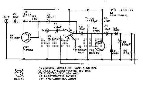
The output is rectified, and TR2 controls the gain of the ICL. This audio compressor circuit uses an MC3340P as a variable gain amplifier. The audio compressor circuit described utilizes an MC3340P integrated circuit, which functions as a variable gain...
The National Semiconductor LMV225 is a linear RF power meter integrated circuit (IC) housed in a surface-mount device (SMD) package. It operates within a frequency range of 450 MHz to 2000 MHz and requires only four external components for...
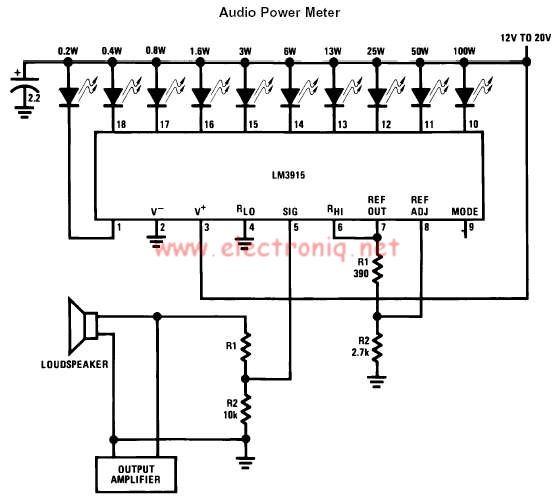
The LM3915 monolithic integrated circuit can be used to design a simple audio power level meter that senses analog voltage levels and drives ten LEDs, LCDs, or vacuum fluorescent displays, providing a logarithmic 3 dB/step analog display. One pin...