
Power amplifier

To design a power booster circuit using the NE5535 operational amplifier, the following components and configurations are essential. The NE5535 is a dual high-performance op-amp known for its low noise and high output current capability, making it suitable for applications requiring increased power.
The circuit typically consists of the NE5535 configured in a non-inverting amplifier configuration to achieve voltage gain. The gain can be set by selecting the appropriate feedback resistor (Rf) and the input resistor (Rin). The relationship between these resistors is given by the formula: Gain (Av) = 1 + (Rf/Rin).
For load driving capabilities, the output stage of the NE5535 should be connected to a suitable load resistor (Rl). The value of Rl must be calculated based on the desired output current and the power supply voltage. It is critical to ensure that the load does not exceed the output current specifications of the NE5535, which can typically deliver up to 100 mA per channel.
When substituting other operational amplifiers for the NE5535, the input current (Icc) specifications should be reviewed, as different op-amps may have varying current requirements. This necessitates recalculating Rl to ensure that the circuit operates within the safe limits of the new amplifier's specifications.
Additionally, the power supply voltage should be within the recommended operating range of the NE5535 to avoid distortion or clipping of the output signal. Bypass capacitors should be placed close to the power pins of the op-amp to filter out noise and ensure stable operation.
In summary, the NE5535 provides an effective solution for applications requiring enhanced power handling capabilities, with careful consideration of load resistance and amplifier specifications ensuring optimal performance.For most applications, the available power from op amps is sufficient. There are times when more power handling capability is necessary. A simple power booster capable of driving moderate loads uses an NE5535 device. Other amplifiers may be substituted only if Rl values are changed because of the Icc current required by the amplifier. R1 should be calculated from the expression.
Related Circuits
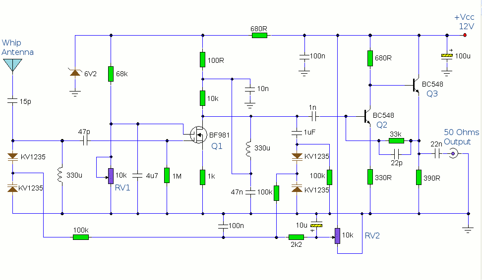
The antenna amplifier circuit comprises approximately 40 components, featuring two NPN transistors (BC548), one MOSFET (BF981), two varicap diodes (KV1235), and a 6.2V zener diode. It includes a 330µH inductor/coil, which can be modified for operation on different frequency...
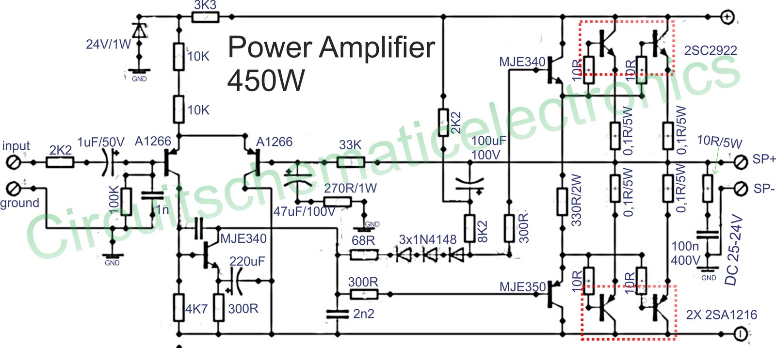
Below is a circuit of power amplifiers with a power output of 450 watts in mono mode. These amplifiers are frequently utilized in high-power applications, suitable for events, and designed for enclosed spaces. This amplifier is appropriate for woofers...
This circuit does not function as effectively as it could. It was created when the designer had a limited understanding of circuit design. An improved schematic will be developed and posted later, featuring a better design. The schematic indicates...
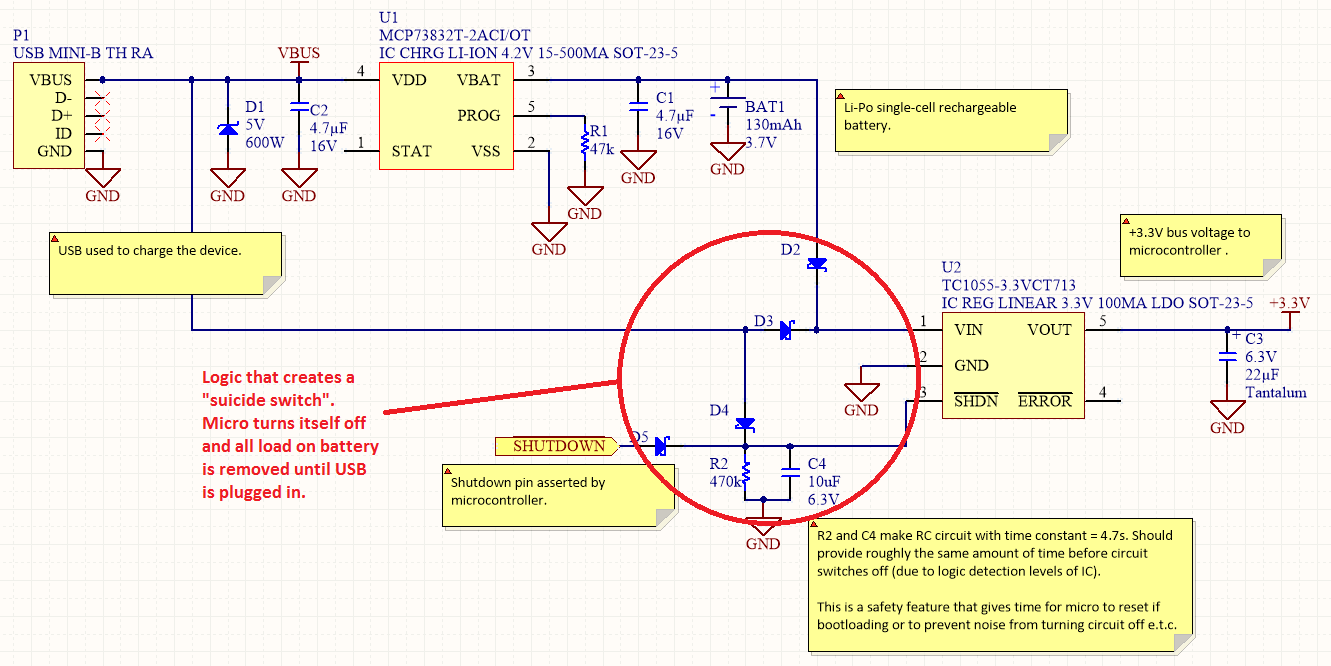
Overview Disabling Sections of a Circuit The "Suicide Switch" Overview Power management is a significant design consideration for battery-powered devices. Power management is a crucial aspect of circuit design, particularly in battery-powered applications where energy efficiency directly impacts the operational...
A radio camera on a model railway is designed to transmit continuously while the train is in motion and to continue transmitting for a few minutes after the train stops. If the train starts moving again after a relatively...

The CMOS 4001 consists of four independent two-input NOR gates. These gates are organized into two pairs. Gates 1 and 2 are connected to form a latching circuit. When the alarm is triggered, they will latch and activate the...