
Power booster

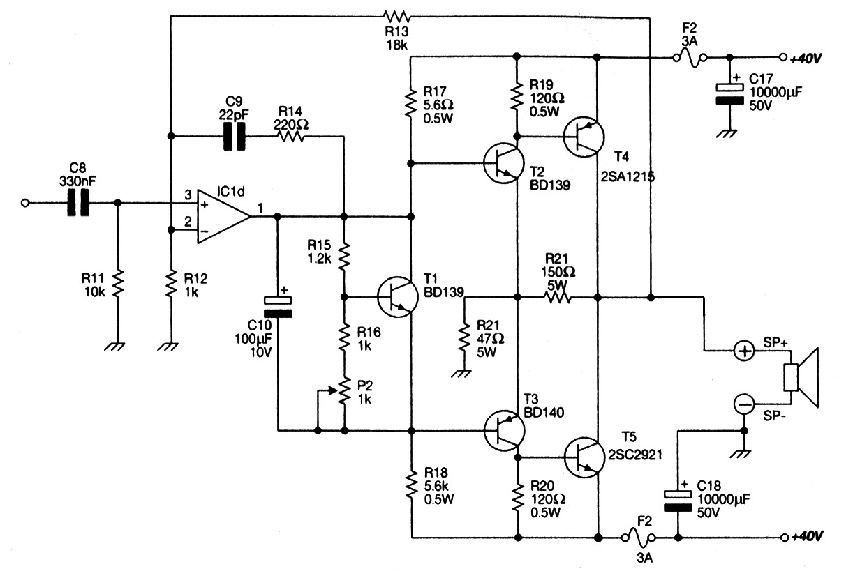
The power booster circuit primarily employs the NE5535 operational amplifier, which is known for its high performance in terms of bandwidth and low distortion. This device is well-suited for applications where moderate load driving capability is essential. The NE5535 features a dual operation, allowing for flexibility in design configurations.
When substituting the NE5535 with alternative amplifiers, it is crucial to consider the supply current (Icc) specifications of the new amplifier. Each amplifier may have different current requirements, which will impact the resistor values in the circuit. Specifically, R1 must be recalculated to ensure that the circuit operates within the desired parameters and maintains stability.
To determine the value of R1, the following expression should be used:
\[ R1 = \frac{V_{supply} - V_{out}}{I_{cc}} \]
Where:
- \( V_{supply} \) is the supply voltage provided to the circuit.
- \( V_{out} \) is the output voltage level required for the load.
- \( I_{cc} \) is the supply current needed by the amplifier being used.
This formula allows for precise tuning of the resistor to accommodate the specific operational characteristics of the selected amplifier, ensuring optimal performance of the power booster circuit. Additionally, careful attention should be paid to the power ratings of all components to prevent overheating and ensure reliability during operation.Power booster is capable of driving moderate loads. The circuit as shown uses a NE5535 device. Other amplifiers may be substituted only if R-l values are changed because of the Icc current required by the amplifier R1 should be calculated from the following expression:.
Related Circuits
This current-limiting circuit, illustrated in this example as part of a small bench power supply, could theoretically be utilized alongside any dual-rail current source. The section of the circuit to the left of the diagram restricts the input current...

A high-power and efficient 100W power amplifier electronic project can be designed using the STK404 audio power amplifier hybrid ICs. These ICs consist of optimally designed discrete component power amplifier circuits that have been miniaturized using SANYO's unique insulated...
Main Power Amplifier OCL 100 watt using MJ802 and MJ4502 transistors. It is designed to provide strong bass and bold treble, making it suitable for various applications such as parties or home theater systems. This Class AB amplifier delivers...
A mixer has been purchased without a power supply unit (PSU). The user does not require the 48V phantom power and is inquiring if an 18V DC wall adapter can be used instead. Additionally, the user seeks information on...
My FM Wireless Microphone has been a very popular project with beginners and experienced constructors alike. It has been used inside guitars and as the basis of a remote control system. I do however, receive many requests for a...
The circuit depicted is utilized in a power supply system to promptly disconnect the power supply in the event of an over-voltage condition during either the grid's on or off phase, thereby protecting the power capacitors. This circuit serves a...