
Capacitance compensation circuit diagram of a power protection

This circuit serves a critical role in safeguarding electronic components by monitoring voltage levels and ensuring they remain within specified limits. It typically employs a voltage sensing mechanism, which may consist of a voltage divider and a comparator. The voltage divider scales down the input voltage to a manageable level, while the comparator compares this scaled voltage against a predetermined reference voltage.
When the input voltage exceeds the reference level, the comparator triggers a response, which may involve activating a relay or a solid-state switch to disconnect the load from the power supply. This disconnection occurs swiftly to prevent damage to sensitive components, particularly power capacitors, which can be adversely affected by excessive voltage.
In addition, the circuit may include transient voltage suppression devices, such as varistors or TVS diodes, to absorb voltage spikes and provide an additional layer of protection. The design should ensure that the components selected can handle the maximum expected voltage and current levels, while also considering thermal management to avoid overheating during operation.
Furthermore, the circuit layout should minimize parasitic inductance and capacitance to enhance response time and reliability. Proper grounding techniques and isolation methods should be employed to prevent noise interference and ensure stable operation. Overall, the implementation of this over-voltage protection circuit is essential for maintaining the longevity and reliability of power supply systems in various electronic applications. Circuit is shown, it is used in the power supply circuit can occur in the case of over-voltage grid on or off phase, promptly cut off the power supply to protect power capacito rs.
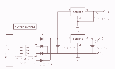
Related Circuits
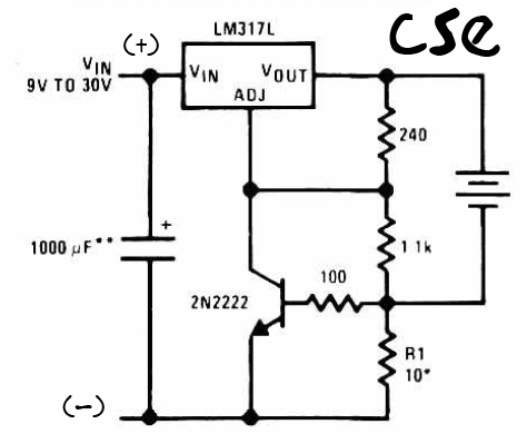
This is a straightforward charger designed for 9V to 30V batteries, primarily operated by the IC LM317L and a 2N222 transistor. It utilizes direct input DC voltage, and a recommended capacitor of 1000µF is included for filtering the output...
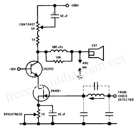
A JFET-bipolar cascode circuit is designed to deliver complete video output for driving the cathode of a CRT. The configuration offers an approximate gain of 90. The cascode arrangement mitigates issues related to the Miller capacitance of the JFET...
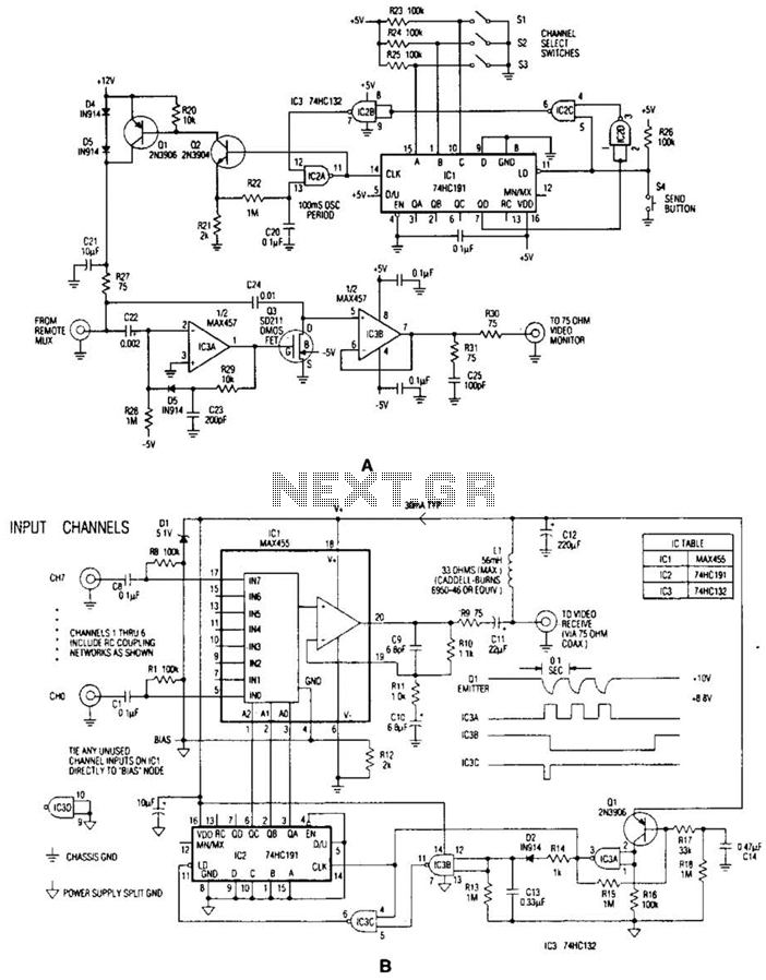
In the video system illustrated in Figures A and R, a single coaxial cable transmits power to a remote location, selects one of eight video channels, and returns the selected signal. This system can choose from several remote surveillance...

A capacitor step-down DC power supply circuit is presented. This circuit eliminates the need for power transformers, utilizing capacitive voltage drop rectification and regulation, which significantly reduces the overall size of the circuit. The circuit includes a capacitor step-down...
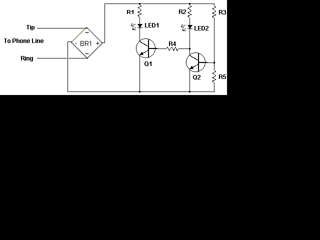
This circuit addresses the issue of phone line interruptions caused by simultaneous use of a modem or fax machine when another phone is picked up. It indicates the status of the phone line by illuminating a red LED when...
The power supply section is the important one. It should deliver constant output regulated power supply for successful working of the project. A 0-12V/500 mA transformer is used for this purpose. The primary of this transformer is connected in...