
Power Control Unit

The power control unit circuit diagram illustrates the primary components and their interconnections for managing electrical power within a system. The main relay, positioned on the left side of the schematic, serves as the central control element, activated by the key switch. This relay is responsible for enabling or disabling the flow of power to various subsystems based on the user's input through the key switch.
The circuit typically includes additional elements such as fuses for overcurrent protection, diodes for flyback protection, and possibly indicator LEDs to show the operational status. The key switch usually connects to the relay coil, ensuring that when the key is turned to the 'on' position, the relay is energized, closing its contacts and allowing current to pass to the downstream circuits.
In more complex designs, auxiliary relays or contactors may be included to manage higher power loads or to provide additional control features. The layout of the circuit should ensure that all components are properly rated for the expected voltage and current levels, with appropriate wire gauges and connection methods to ensure reliability and safety. Each component should be clearly labeled in the schematic to facilitate understanding and troubleshooting by technicians or engineers who may work with the circuit in the future.This a shows the overall circuit diagram of the power control unit. On the left, there is a main relais controlled by the key switch and the .. 🔗 External reference
Related Circuits
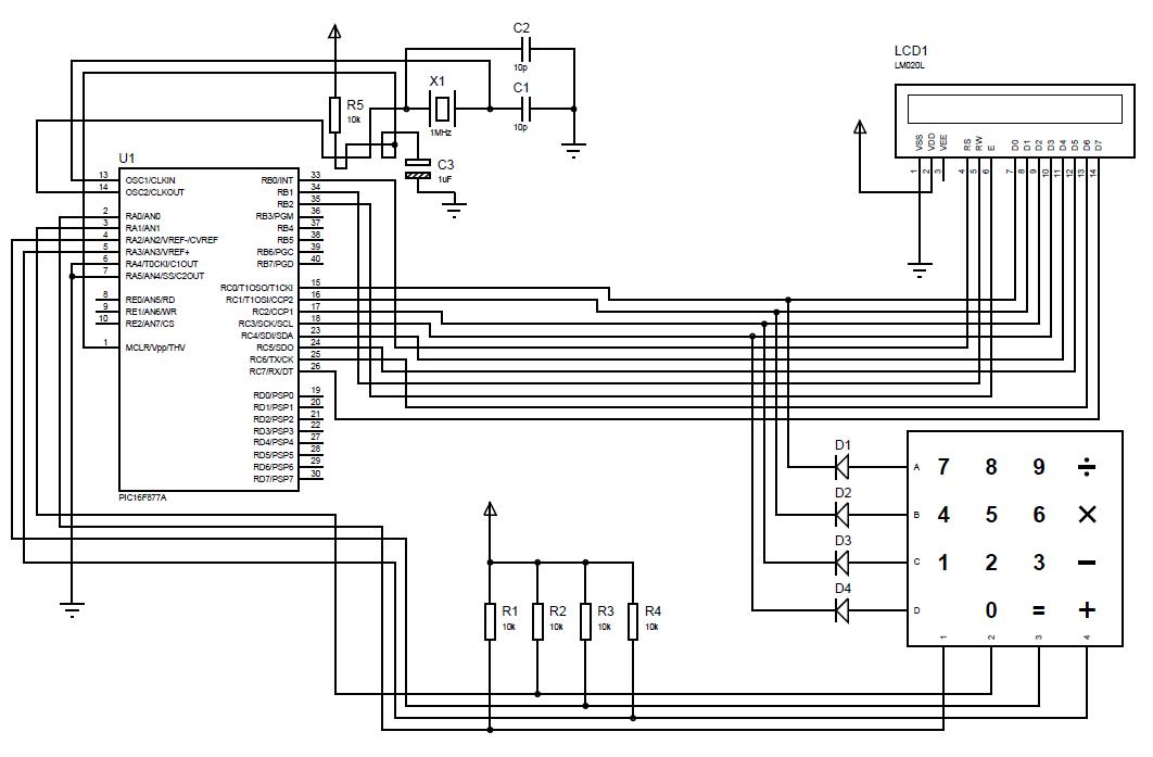
A beginner or hobbyist is seeking to learn more about microcontrollers. The objective is to display an output on an LCD when a button on the keypad is pressed. To achieve the desired functionality of displaying output on an LCD...

This circuit performs a rapid battery test without requiring a power supply or costly moving-coil voltmeters. It features two ranges: when SW1 is configured as depicted in the circuit diagram, the device can test batteries ranging from 3V to...
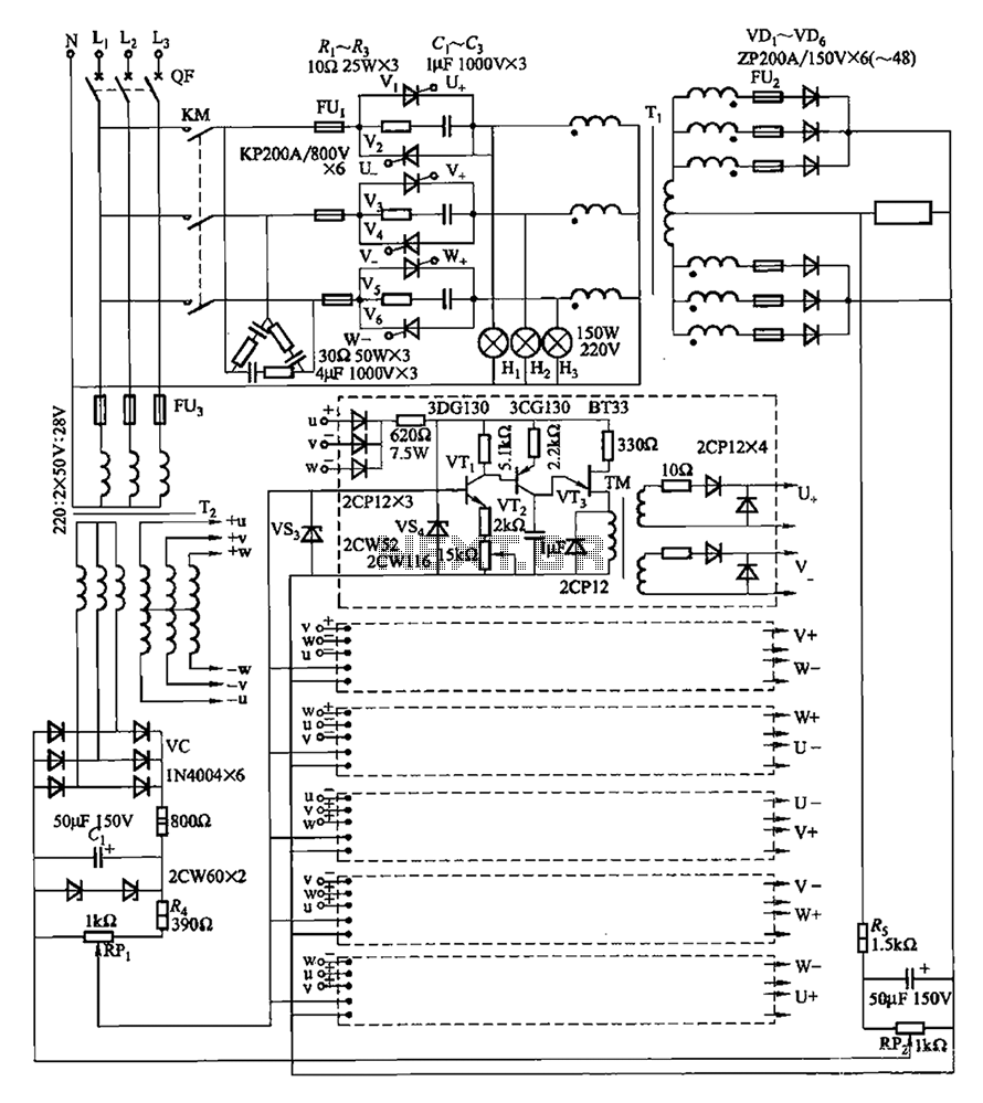
A three-phase thyristor power regulator circuit designed for plating applications, capable of handling currents from 1200A to 6000A at a voltage of 10V. The circuit comprises a main circuit, a trigger circuit, synchronous power components, and a voltage negative...
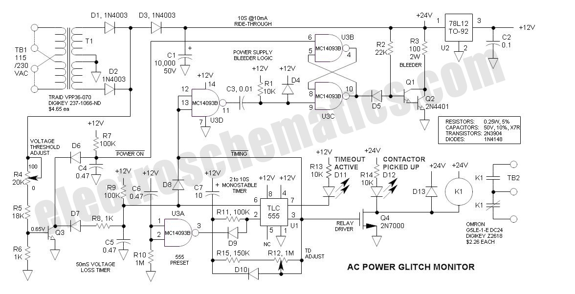
This AC Power Monitor continuously monitors the AC power line voltage for both under-voltage conditions and missing cycles. When it detects a total of 5 or 6 consecutive missing half-cycles (50ms, 50/60Hz), it activates a relay and initiates a...
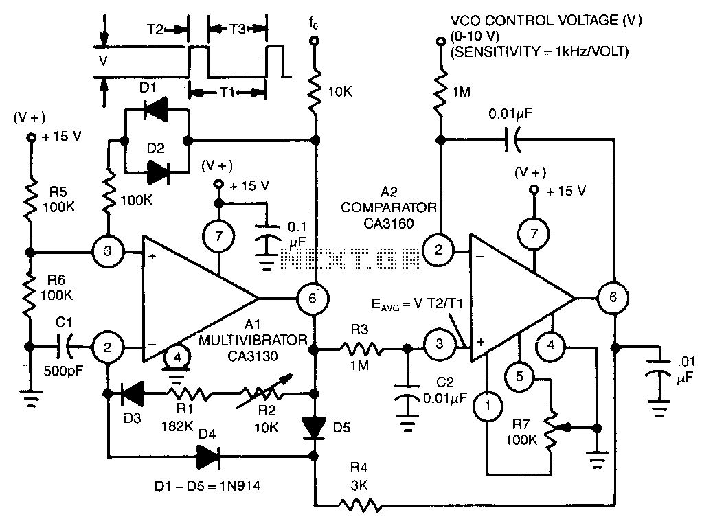
This circuit utilizes a CA3130 BiMOS operational amplifier as a multivibrator and a CA3160 BiMOS operational amplifier as a comparator. The oscillator exhibits a sensitivity of 1 kHz/V, with a tracking error of approximately 0.02% and a temperature coefficient...
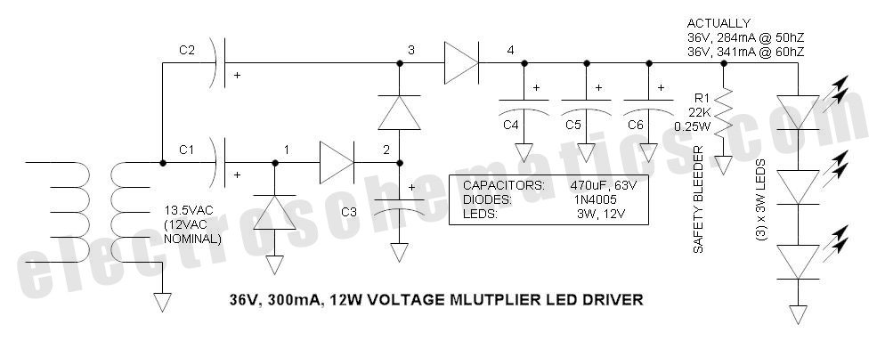
This power supply circuit is designed around a standard 12VAC landscape lighting transformer. The availability and selection of transformers have long posed challenges for experimenters, often leading them to use potentially hazardous off-line capacitor-limited power supplies. However, the widely...