
Temperature Controlled NICD Charger

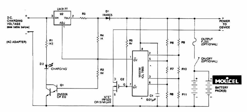
The described circuit functions as a temperature-controlled constant current battery charger, specifically designed for nickel-cadmium (NiCd), nickel-metal hydride (NiMH), and similar rechargeable battery types. The fundamental operation relies on the thermal response of the batteries; as they reach full charge, their internal temperature rises, which is monitored to prevent overcharging—a significant factor in prolonging battery life.
The initial power stage of the circuit includes a transformer that steps down the AC mains voltage to a lower AC voltage suitable for charging. Following this, a bridge rectifier converts the AC voltage to pulsating DC, which is then smoothed by a 1000µF capacitor, resulting in approximately 22V of DC power. This voltage is necessary to ensure that the subsequent components in the circuit receive adequate power.
To regulate this voltage, a 7812 voltage regulator is employed, which steps down the voltage to a stable 12V. This regulated output is crucial for the operation of the LM311 voltage comparator and the 4011 NAND gates that are integral to the control logic of the charger. The LM311 comparator serves to monitor the voltage across the battery, while the NAND gates are used to implement the control logic that manages the charging process.
The circuit is initiated by pressing a start switch, which activates the charging sequence. This switch connects the power supply to the charging circuitry, allowing the charger to begin monitoring the battery's voltage and temperature. The control logic ensures that the charging current remains constant until the battery temperature indicates it is fully charged, at which point the charging process is halted to prevent damage from overcharging.
In summary, this temperature-controlled constant current battery charger is a vital circuit designed to safely charge rechargeable batteries while monitoring their thermal characteristics to prevent overcharging and extend battery life. The combination of a transformer, rectifier, smoothing capacitor, voltage regulator, comparator, and logic gates creates a robust and efficient charging solution.This circuit is for a temperature controlled constant current battery charger. It works with NICD, NIMH, and other rechargeable cells. The circuit works on the principle that most rechargeable batteries show an increase in temperature when the cells becomes fully charged. Overcharging is one of the main causes of short cell life, hot cells pop their internal seals and vent out electrolyte.
As cells dry out, they lose capacity. The transformer, bridge rectifier, and 1000uF capacitor provide around 22 Volts of DC power to run the rest of the circuit. The 7812 regulator drops this to 12V to run the 311 comparator and 4011 nand gates. The start switch is pressed to start the cha 🔗 External reference
Related Circuits
As the circuit operates, the three sets of diodes with their isolation capacitors build up an increasing voltage on capacitor C1. The voltage at point B will also increase and be about twelve volts less than the voltage on...
A constant-current/constant-voltage linear charger for single-cell lithium-ion (Li-ion) batteries can be constructed using the EUP8054 battery charger controller chip and a few passive components. This compact integrated circuit is suitable for various portable devices and is compatible with USB...
The charging system described is designed for multi-cell lithium battery packs comprising two to six series-connected cells or series/parallel configurations. The schematic diagram originates from the lithium battery charger power supply circuit. This circuit is specifically intended for charging...
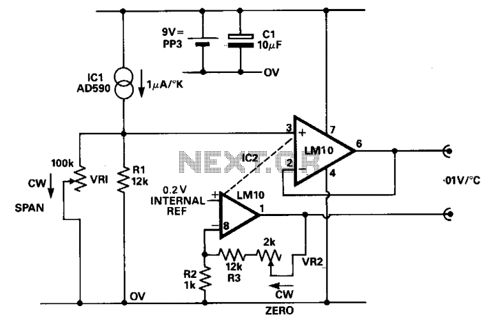
The digital voltmeter (DVM) provides a direct reading of the sensor's temperature in degrees Celsius. The temperature sensor IC1 generates a nominal 1 µV per degree Kelvin, which is converted to 10 mV per degree Kelvin by resistors R1...
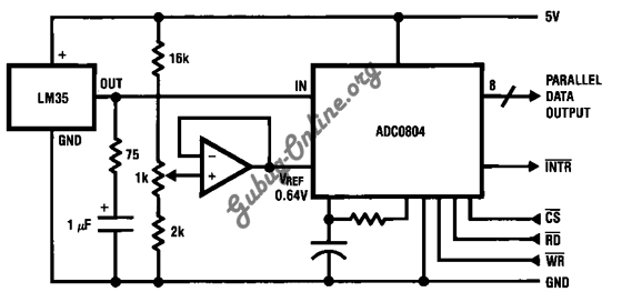
This is a design for a temperature-to-digital converter circuit that is controlled by the LM35 integrated circuit. The LM35 is a precision integrated circuit temperature sensor, whose output voltage is linearly proportional to the Celsius temperature. The circuit utilizes the...
Battery manufacturers recommend charging 12V lead-acid batteries at a charge voltage of 13.5 - 13.8V for standby, and 14.4V - 15V for cyclic use (charging and discharging). However, when using the latter option, which allows for a faster charge,...