
Power LED mood Lamp

- 3 x NPN transistors capable of driving 500 mA, for example, the BC337
- one PIC 16F628(A) and a programmer
- a small perforated circuit board
- 7 x 10K resistors (1/4W)
- some 1 watt resistors (4.7, 10, and 15 Ohm) and a DIP switch
- a power supply (5 volts, 500 mA)
- Ikea Mylonit lamp or other housing
- silicon paste from your local DIY shop (if you want to use a heatsink)
- one z-power 3 watt RGB LED
- a little heatsink and some cooling paste (if you want to use a heatsink)
The project described involves creating a LED mood lamp utilizing a PIC16F628 microcontroller for color control, alongside a simple transistor-based switching circuit. The circuit design incorporates three NPN transistors, such as the BC337, which are capable of handling a maximum current of 500 mA, ensuring adequate power management for the RGB LED. The use of a 5V power supply rated at 500 mA is appropriate for this application, considering the maximum current draw of 232 mA when all colors are activated simultaneously.
The programming of the PIC16F628 microcontroller is facilitated by a straightforward PIC programmer and software called ic-prog, where the user uploads a .hex file to configure the microcontroller's operation. Special attention must be given to the configuration of fuse bits to ensure the microcontroller operates correctly in the intended application.
Resistors are utilized in the circuit to limit the current flowing through the LED and transistors, with seven 10K resistors (1/4W) and additional power resistors of 4.7, 10, and 15 Ohms being specified. The inclusion of a DIP switch provides a means of adjusting settings or modes within the circuit.
To physically mount the circuit board, the use of a hot glue gun is recommended to secure the board within the lamp housing, ensuring it remains in place during operation. The project may also benefit from the application of silicon paste and a heatsink to dissipate heat generated by the power components, enhancing the longevity and reliability of the circuit.
Overall, the schematic and components outlined form a cohesive design aimed at creating an aesthetically pleasing and functional LED mood lamp, with flexibility in color output and ease of assembly.A good way to mount the circuit board is to use a hot glue gun to "mold" the circuit underneath the lamp housing. There is plenty of space there for your board. At the next photos you can see the circuit board mounted on the small 31cm IKEA Mylonit Lamp. It's clear that current changes as colors are changing. As you can see the max current needed is 232mA. You should keep in mind that this depends on the led you have and the power resistors you choose. As a conclusion a power supply rated at 5V/500mA will be sufficient. The schematic used is shown in the next image. It's as simple as it shows. Take care on the correct transistor mount and correct polarity of power source. Programming the PIC16F628 can be achieved using this very simple pic programmer and a program called ic-prog. Just use your programmer and upload the .hex file on your PIC. For successful results you should pay attention on the fuse bits. You should enter the correct fuses as noted on the following table. Here is a list of the components i used for making the led mood lamp. - 3 x NPN transistors capable of driving 500 mA, for example the BC337 - one PIC 16F628(A) and a programmer - a small perforated circuit board - 7 x 10K resistors (1/4W) - some 1 watt resistors (4,7, 10 and 15 Ohm) and a DIP switch - a power supply (5 volts, 500 mA) - Ikea Mylonit lamp or other housing - silicon paste from your local DIY shop (if you want to use a heatsink) - one z-power 3 watt rgb led - a little heatsink and some cooling paste (if you want to use a heatsink)
🔗 External reference
Related Circuits
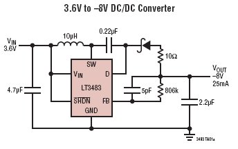
The LT3483/LT3483A are micropower inverting DC/DC converters featuring integrated Schottky diodes and a single resistor feedback mechanism. Their compact package size, high integration level, and the use of small surface mount components allow for a solution size as small...
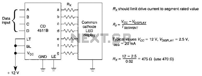
A CD4511B CMOS LED display driver can be utilized to operate a common cathode LED display. Current limiting resistors are employed to restrict the segment current to the specified value at the maximum supply voltage. The CD4511B is a...
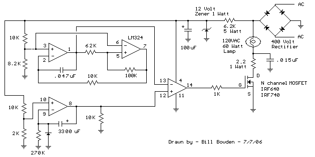
This circuit gradually illuminates a 120VAC lamp over an approximate 20-minute period. A bridge rectifier converts the AC voltage to 120V DC, supplying power to the MOSFET and the 60-watt lamp. A 6.2K, 5-watt resistor along with a Zener...
A dual benefit for battery-powered portable devices is provided by Class D audio amplifiers. They produce much less power dissipation than their linear counterparts. Class D audio amplifiers, also known as switching amplifiers, are designed to achieve high efficiency and...
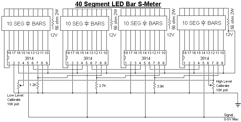
Provide your radio with an actual cord signal. First, adjust the HIGH LEVEL potentiometer to the point where all LEDs are illuminated. Then, completely remove the signal and adjust the LOW LEVEL potentiometer until no LEDs are lit. If...
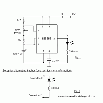
When the preset is set to its maximum, the LED flashes approximately every half second. This flashing rate can be increased by using a larger capacitor value, for instance, changing from 10µF to 22µF will result in a flashing...